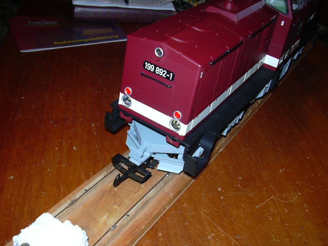
Conversion of a german diesel locomotive "Harzkamel" to battery operation and radio remote control using Planet5B (2.4 GHz) |
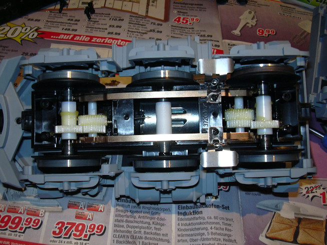
First the sliders were removed from the bogies. in the In contrast to LGB locomotives, this Piko locomotive does not have any graphite grinders built in, but copper sheets that are resilient on the conductive Grind semi-axles. The sliders are still in here, those middle axes are not used, neither for power consumption nor for the drive.
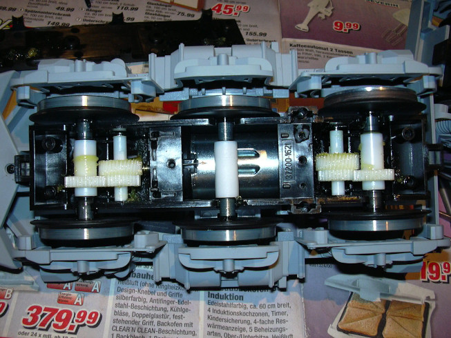
This picture shows a bogie with removed sliders.
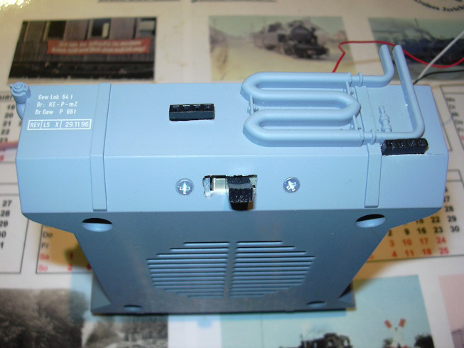
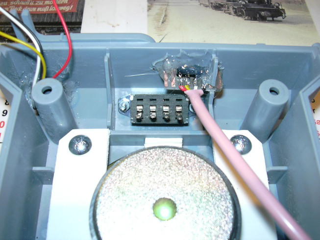
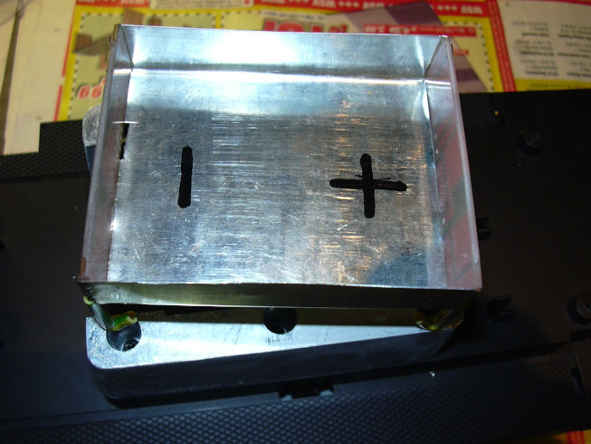
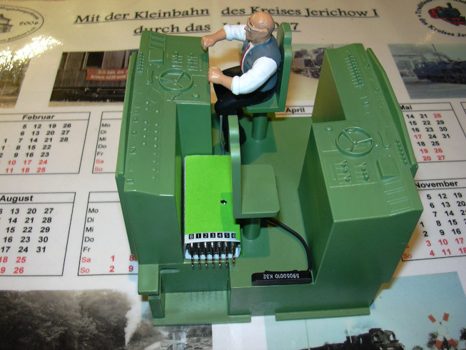
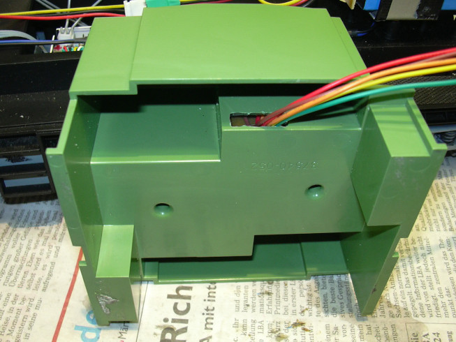
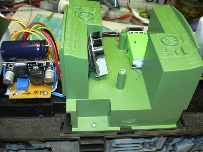
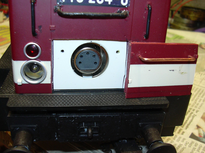
This picture shows the "diesel tank" with the control panels already installed. The battery switch is built into the slope. Above it the charging socket for the batteries is located on the surface. Bottom right under the coil can see the PC interface.

The same thing again from a different point of view.
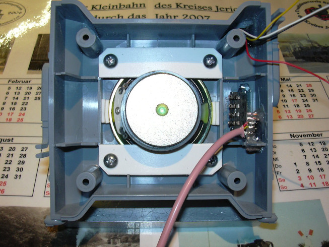
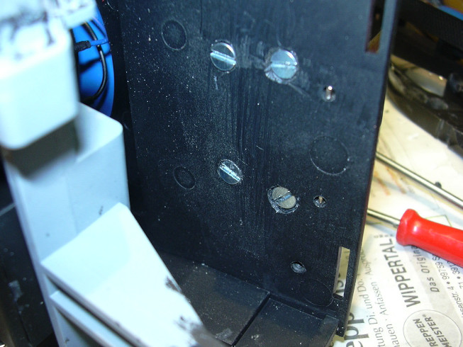
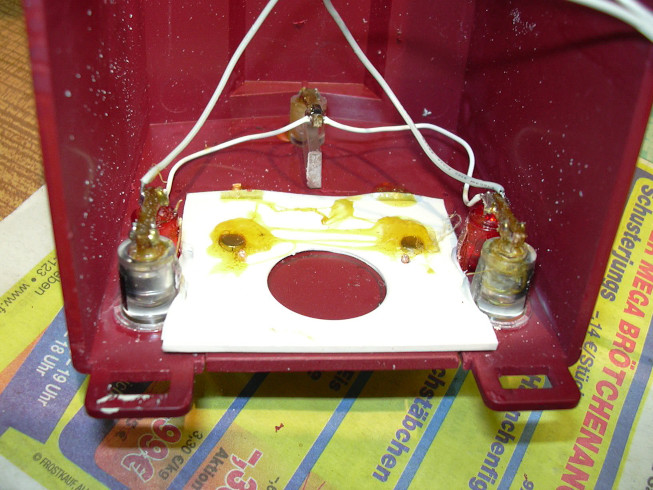
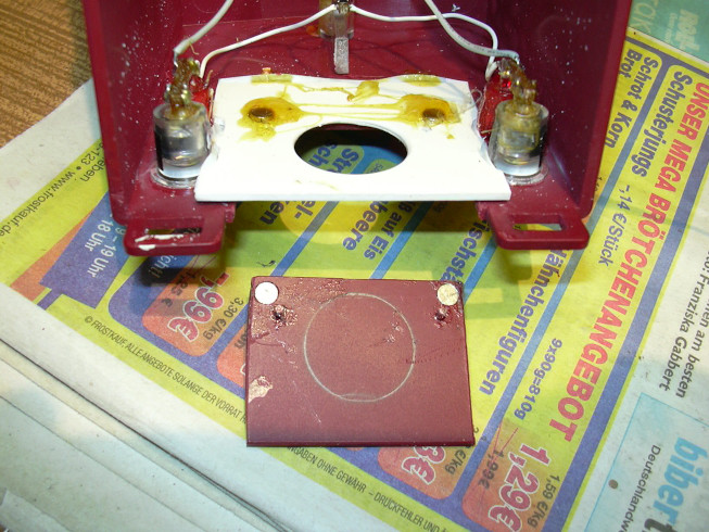
The inside of the diesel tank. The loudspeaker was screwed on by means of two lugs. Intermediate layers made of foam rubber and double-sided adhesive tape secure the loudspeaker against slipping.
The charging socket was glued in with hot glue and a soldering iron, as well as the socket of the PC interface. The slide switch was screwed in with M2 screws and nuts.
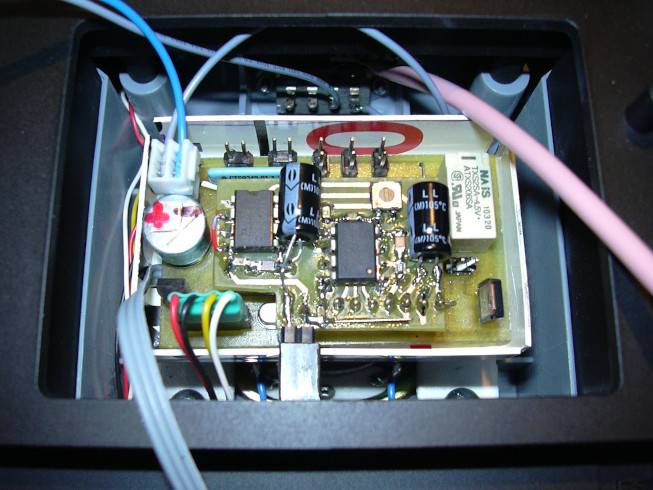
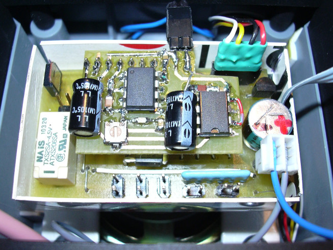
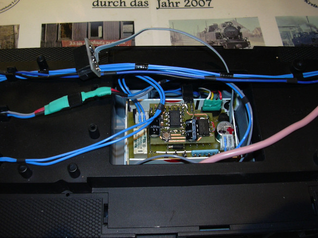
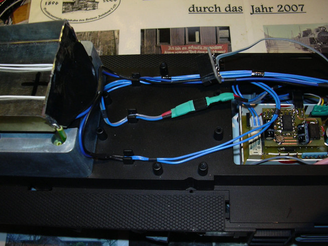
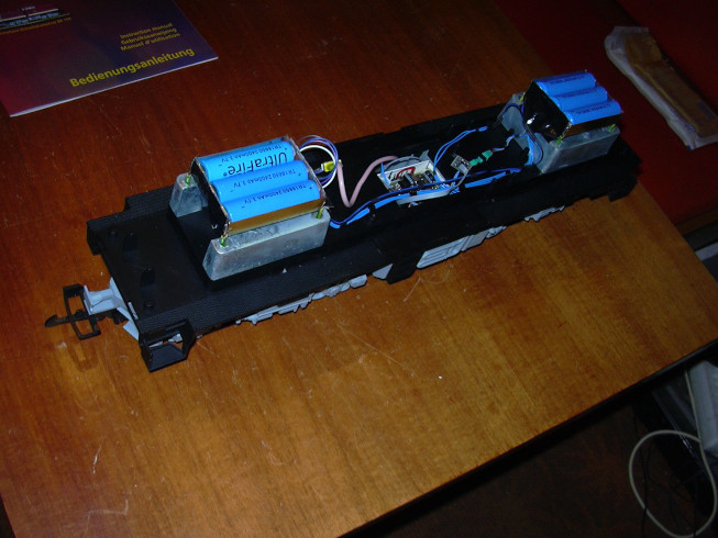
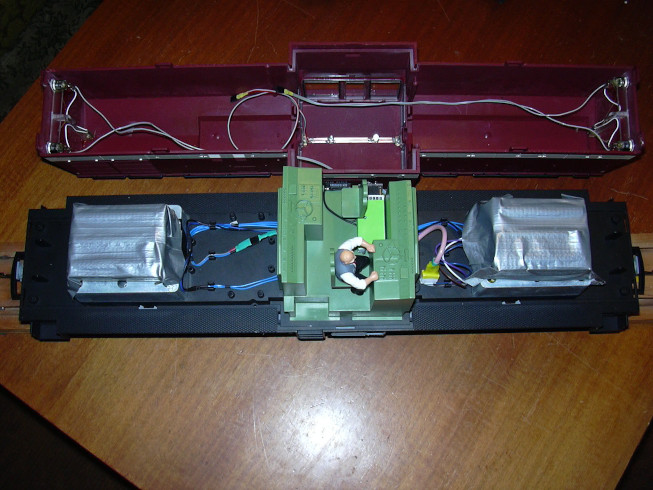
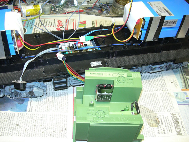
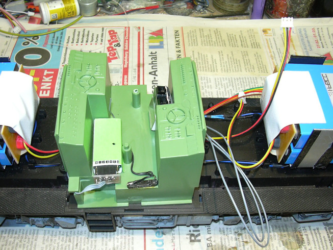
Now the diesel tank and its contents are located back under the locomotive frame. On the magnet of the speaker a box made of PVC (1 mm) is stuck on double-sided adhesive tape, in which the locomotive controller and the attached sound module are in place. One piece of double-sided adhesive tape secures the circuit board from falling out. Speakers, PC interface, switches and power supply are included already connected. The large opening in the frame offers enough space of movement for connecting the additional electrical assemblies.
And again up close, from left to right at the top: power supply, front light, rear light, switch function 3, switch function 2, switching function 1. Bottom from left to right: receiver (fixed Ribbon cable), extension of the PC interface, loudspeaker (upper Circuit board) and motor connection (directly on the relay).
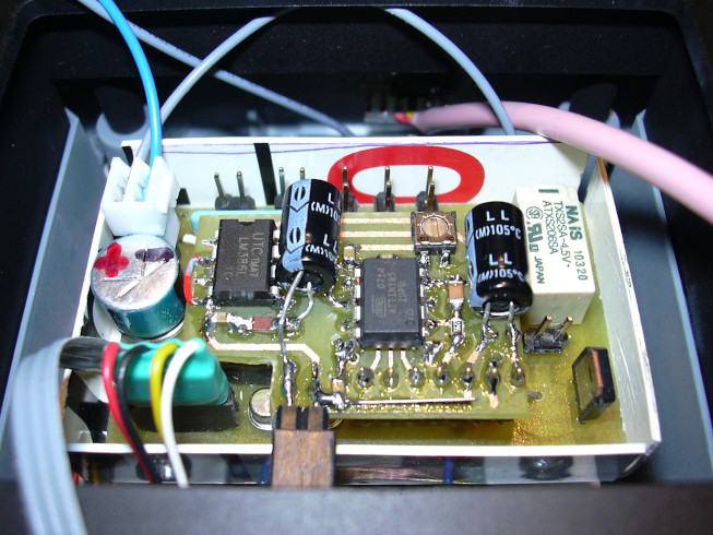
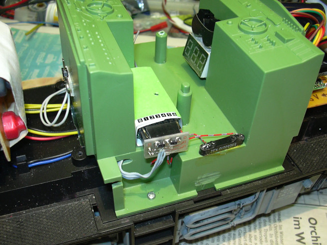
View from the other side. The volume can be adjusted with the trim potentiometer at the lower edge of the sound board.
View from a distance to clarify the size proportions.
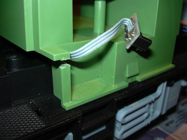
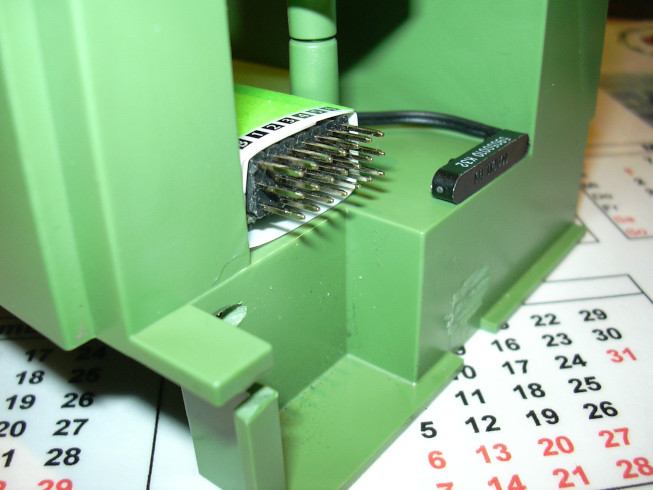
This incision (with the flex) creates space for the implementation of the receiver cable into the driver's cab. The photo shows that I still have to deburr something there.
Here again from a slightly different point of view. In the intention of easy accesssibility of service it makes sense, to grind the locking lugs of the the interior part of the driver's cab and to screw the entry area onto the frame. If the upper part of the housing clicks into place, there will be trouble with the receiver line.

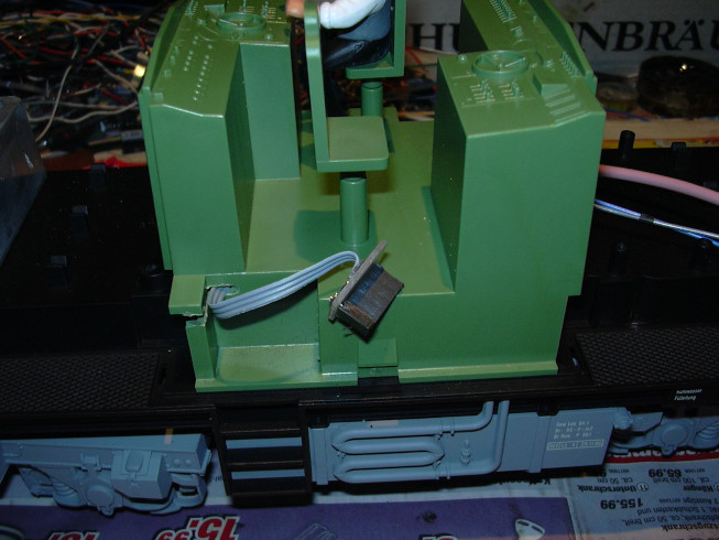
Again the other side, between the frame and the inside of the driver's cab there is enough space for the cables to pass through.

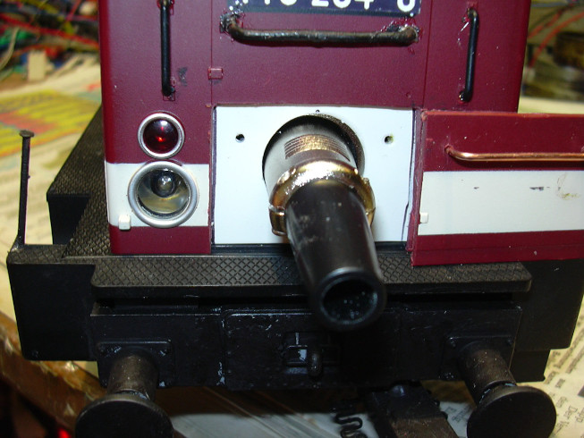
Here is the diesel tank again with the controls in the attached state to see. The charging socket is now inside the entry ladder.
The housing of a battery chamber. The contacts are not installed yet.
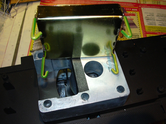
Underside of the battery chamber, the mounting feet are in the outer holes of the weights inserted and clamped there quite tight, but can be solved again.
The contact plates are now built into the battery chambers. The plus side is rigid, the minus side is spring-mounted.
You can see the contacts better from this point of view.
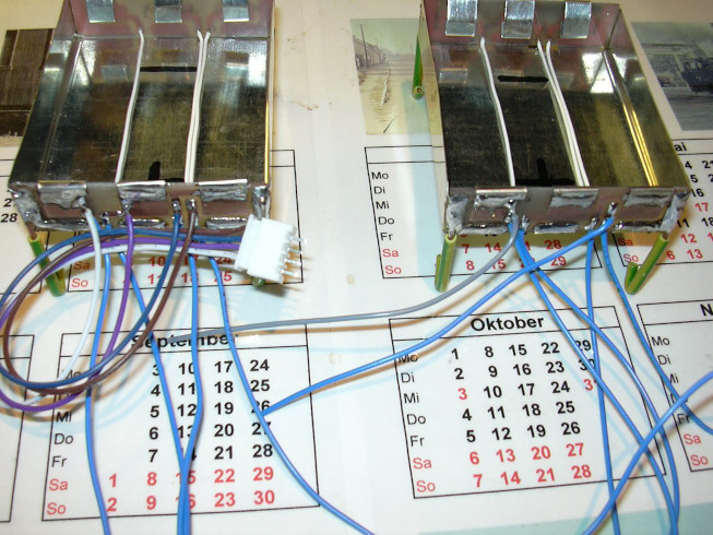
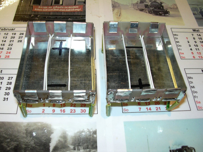
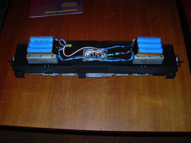
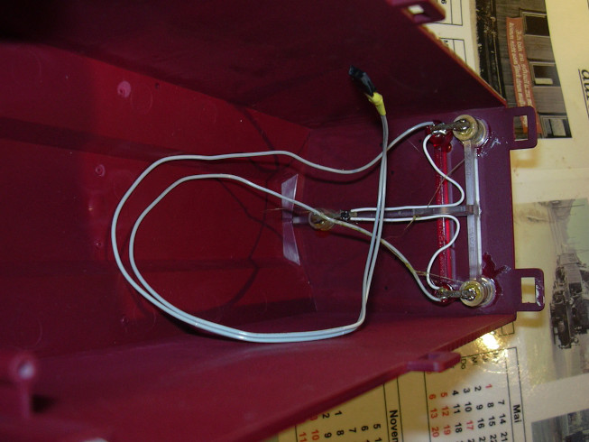
The fully wired battery chambers. Both chambers are parallel switched, also the taps between the cells. At the left ventricle is the connection for the charging cable, on the right chamber the connection for the speed controller.
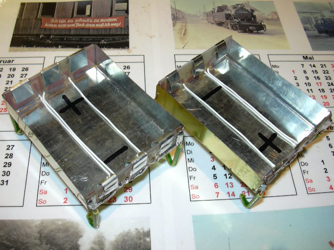
The weights as well as the undersides and connection boards of the chambers were masked with textile tape to prevent chafing of the cables. The motor cables are located beneath the battery chambers.
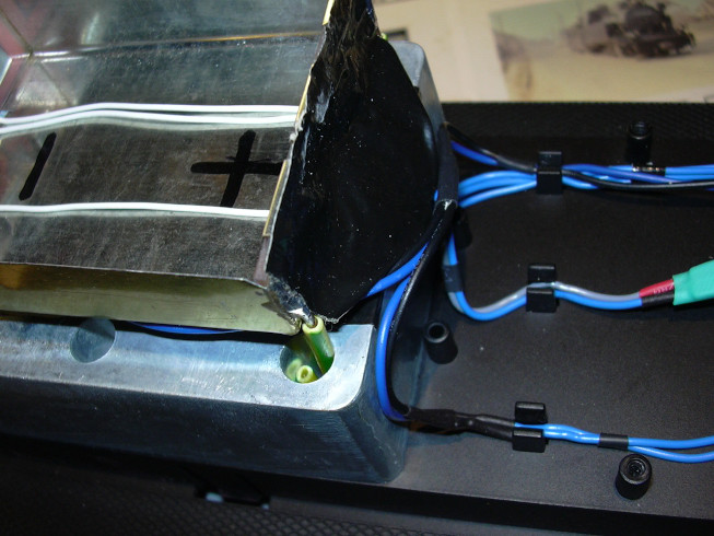
The other battery chamber with the connection of the charging cable via plug connector.
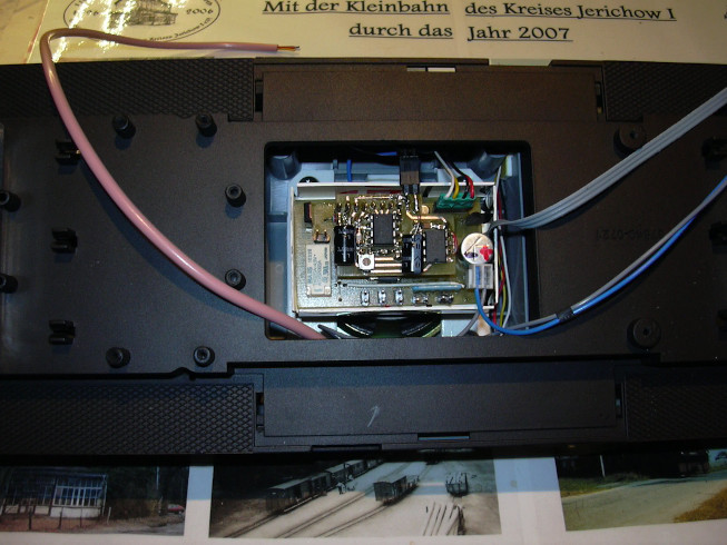
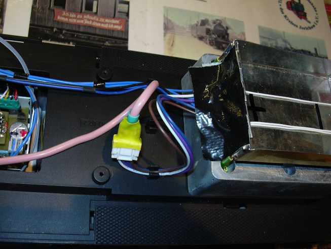
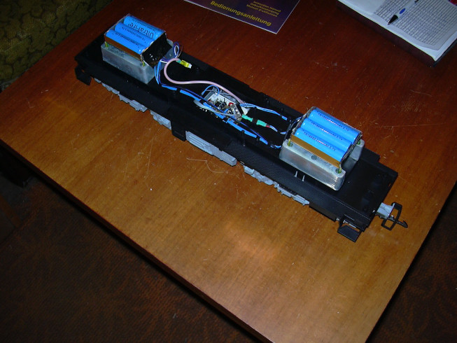
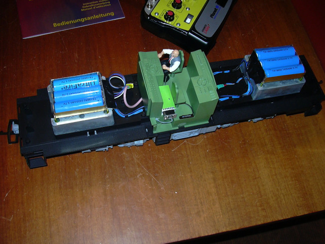
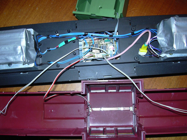
The upper cable bundle connects the battery chambers with 4 wires and with 2 wires the motors. Above that is the connection for the radio receiver. The middle cable on the left (2 wires) is the power supply to the speed controller. A connector was also used here. Colored sshrink tubes (red / black) are used to recognize the polarity. The lower cable (2 wires) on the left leads to the motors. The pink cable is the charging cable at the bottom right side.
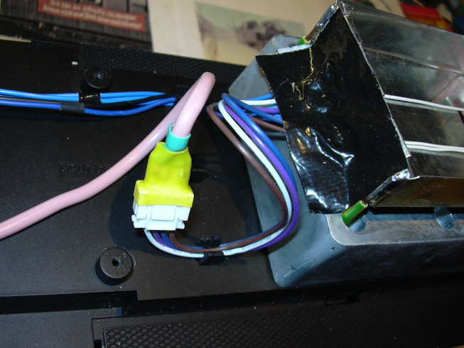
Same again on the left ...
... and further to the right.
Just like that with the interior part of the driver's cab.
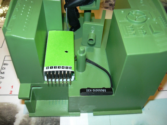
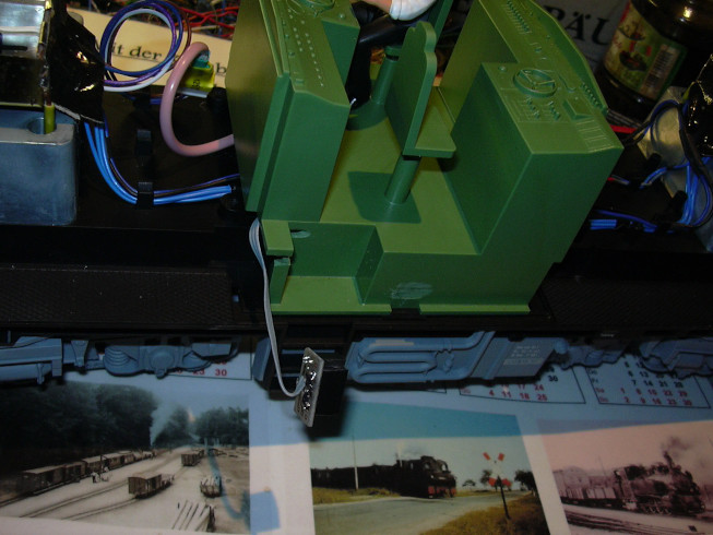
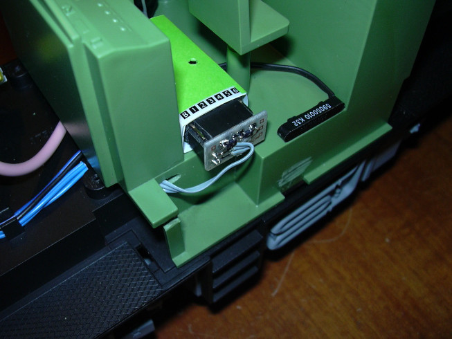
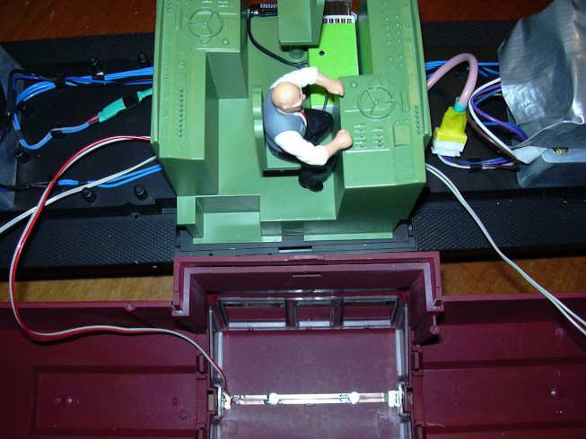
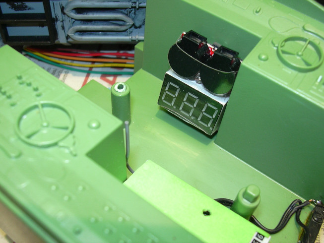
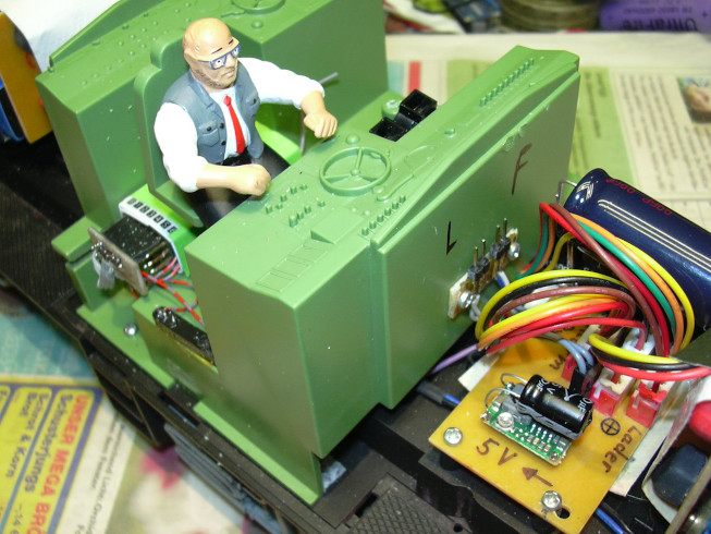
The installation of the radio receiver. Since it doesn't stand out so much, some green paper was pasted over it. With the reed contact on the right front side, the receiver is tuned to the respectve transmitter by using a magnet from outside.
The same thing again with the seat installed again. Receiver and reed contact were made using a glue roller .
Again up close, you can also see that the slot for the The receiver cable has now been deburred and that the locking lugs for the Upper part of the housing (bottom right) was flexed.
Now the batteries are also inside.
View from the right ...
... and from the left.
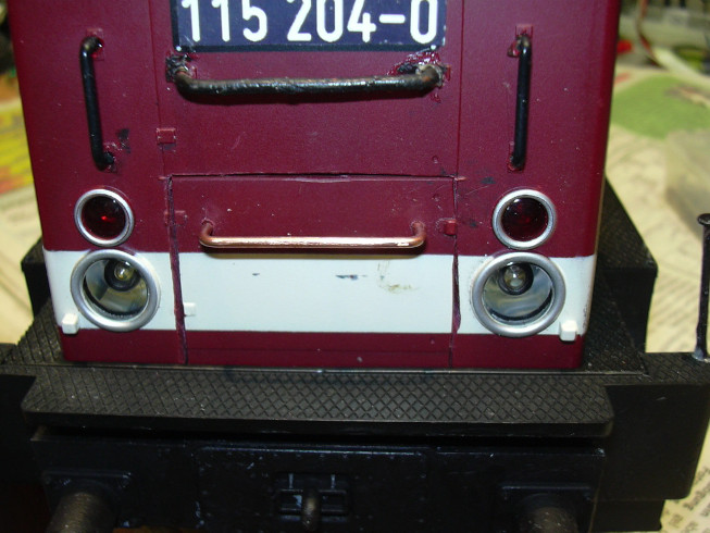
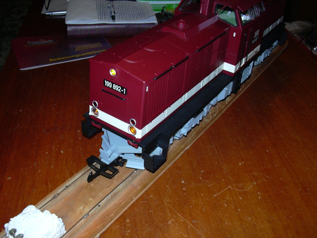
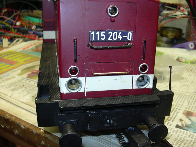
The Harzkamel as a convertible. Driving, ringing and honking already works.
Connection of the radio receiver.
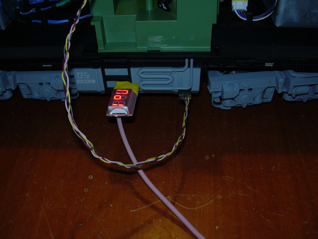
The charging of the batteries and the connection to the PC now works. The speed controller was set to address 1. The remaining settings of the speed controller correspond to this file , it can be loaded into the Windows program "lokparameter", where it is displayed graphically.
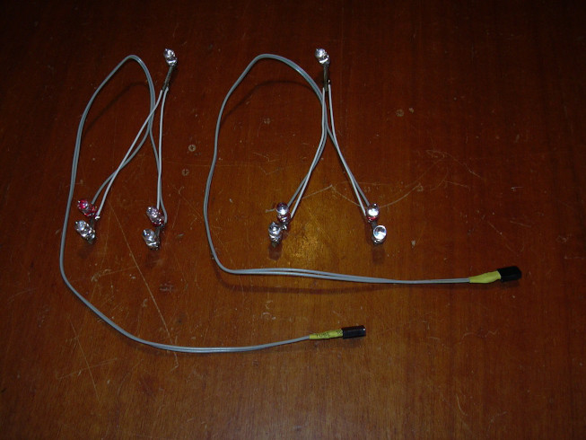
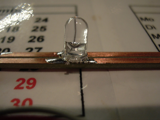
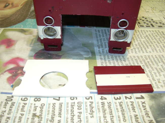
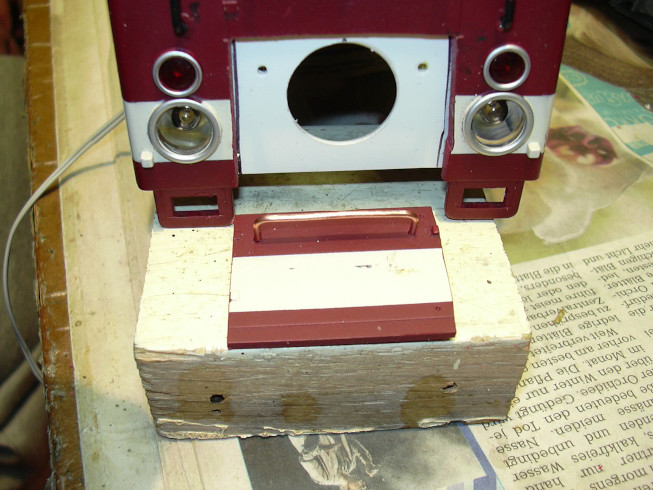
The lamp sets for the headlights. For the lower headlights red and yellow LEDs were switched anti-parallel, the upper ones Headlights got an anti-parallel SMD diode on the Circuit board strips. Strips were made to fix the connections double-sided board material used. Round LEDs with 5 mm diameter had been used. Originallly, round LEDs with a diameter of 3 mm had been considered, but the mechanical effort involved in installation would havee been significantly higher. The headlights are designed for LEDs with a diameter of 5 mm.
The LEDs were fixed in the headlights with some contact adhesive bby UHU.
The adhesive pulls threads, but remains elastic if it is not used as a contact adhesive.
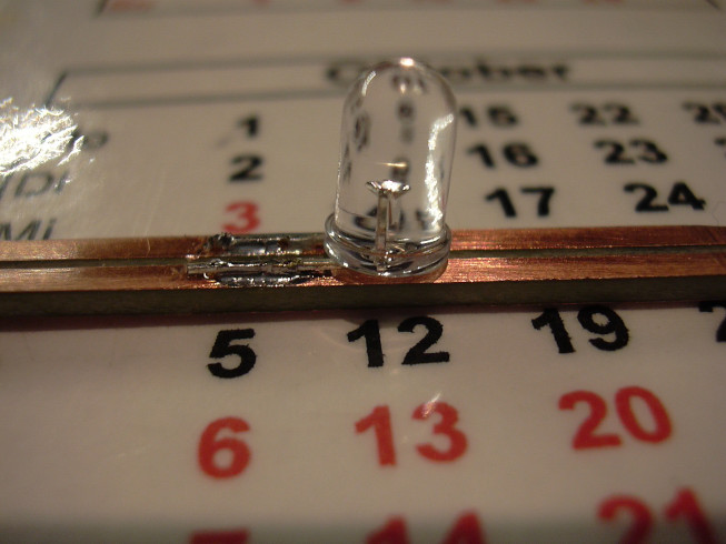
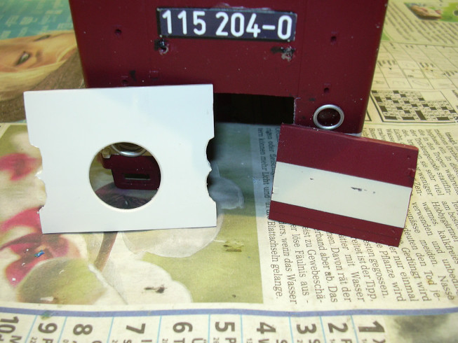
Here you can see the circuit board strip as an LED carrier quite well.
The 3 yellow LEDs on each side are connected in series, at reversed polarity are the two red LEDs and an SMD diode in series switched. The current is limited by the speed controller, the LED circuit therefore works without a resistor.
The other side of the case.
Here, the LEDs were fixed with glue too.
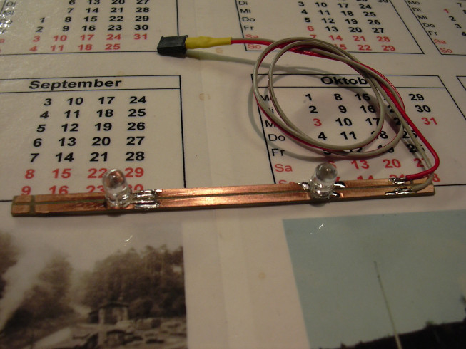
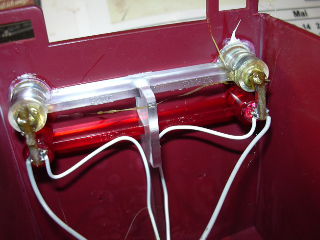
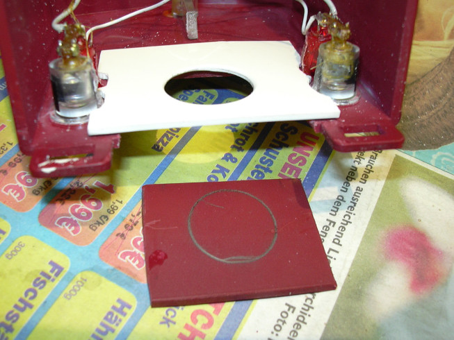
The cab lighting. Here are two yellow LEDs and one 910 Ohm SMD resistor connected in series. The SMD resistor is covered by the right LED.
The LED with the resistor located underneath.
The other LED.
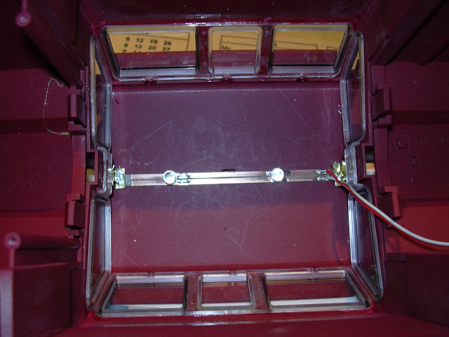
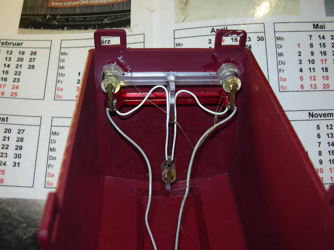
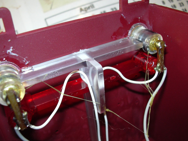
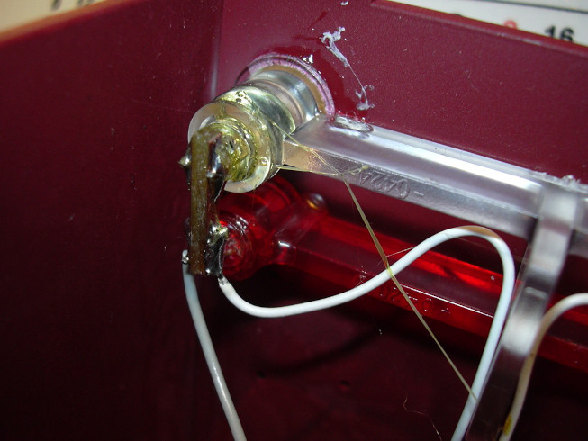
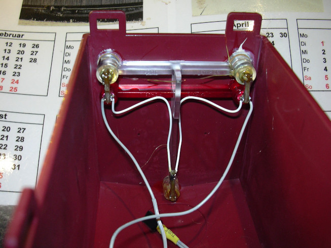
The built-in light bar. The sheet metal springs at the ends clamp under the window bars.
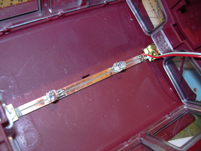
Again from a different perspective, you can see it on the right how the sheet metal angle stuck under the web. A fixation with glue was not necessary.
To protect the headlight cables from damaging at the sharp edges of the battery chambers, the batteries were covered with textile tape covered.
Now the headlights and the interior lighting are connected, the interior lighting is currently incorrectly polarized and on the wrong connection is plugged. In the meantime it is correctly polarized Switching function 3.
The inner part is put back on and the cables of the upper part are aligned on such a way that they cannot be pinched.
The yellow headlights switched on are not particularly well hit by the flash.
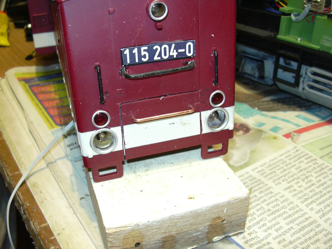
The red rear lights are now switched on.

The housing is closed, the latches are locked in place, the buffer planks and the 8 screws are still lacking. They are now already on it, but I didn't take a picture of it.
Now comes a test drive under realistic conditions. this happens at an exhibition where some garden railroad fans have a layout and let their trains run. Some other traction vehicles with battery operation came Planet rdio control into operation.
... and then this crazy wheelchair user comes up with the idea of installing LiFePo batteries with higher performance ....
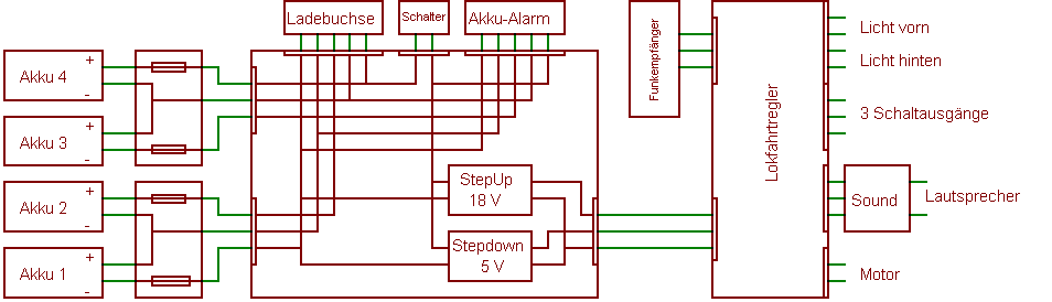
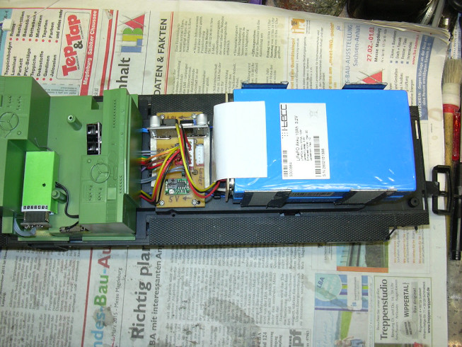
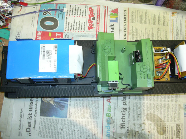
There were 4 lithium iron phosphate battery cells each 3.2 V, 10 Ah with M6 connection bolts inserted. Every 2 cells share one Contact board which, in addition to the contacting, also has one for each cell Contains fuse in the form of a thin sacrificial wire. From there it goes to the power distribution board with two balancer cables (2s). There both 2s cell groups are interconnected to form a 4s battery. The connection for the charging socket is located parallel to this. The plus will be over the battery switch to connect the battery alarm and to both switching regulators out. The battery alarm was made with electronics all-pole disconnection / activation of the alarm module retrofitted, it must so when switching off only the plus are switched off.
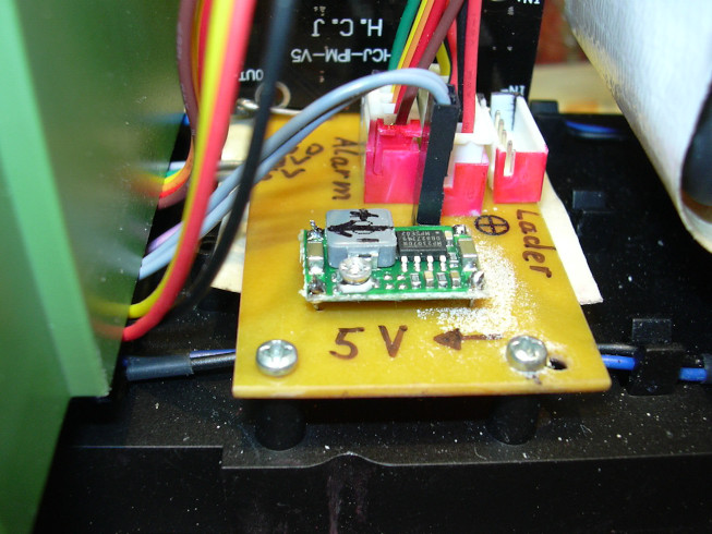
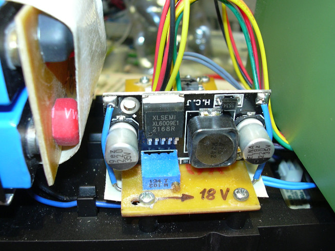
A stepUp switching regulator generates around 18 V from the battery voltage for traction motors and lights. A stepdown switching regulator generates from the battery voltage 5 V for the microcontroller of the locomotive speed controller and sound module, as well as for the radio receiver.
The multi-function locomotive speed controller reads via wired OR wiring with diodes the servo channels 1, 3 and 5 of the radio receiver on and decodes channels 1 to 5 from this. Channels 1 are used (Keyboard), 2 (driving channel A), 3 (driving channel B) and rarely also 4 (Driving channel C). In addition to controlling the traction motors, the speed controller also controls the lighting, three function outputs and the sound module.

They are screwed onto the batteries in such a way that the copper layer is on the inside.
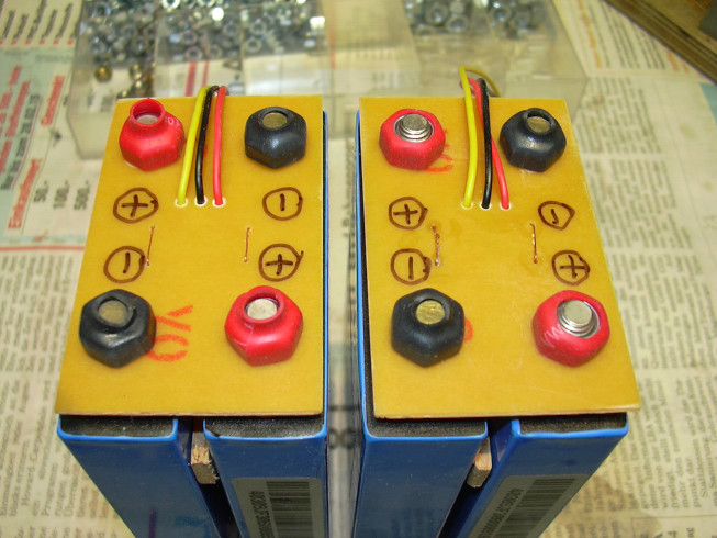
The fuses in the form of sacrificial wires can also be seen here. These fuses are not used to limit the current during operation, the speed controller has its own fuse. They serve to protect the batteries, from accidentally short-circuits while working on the electronics. Because these batteries deliver currents with which you could almost weld ... 8-(
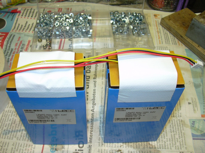
The insides of the well-deburred retaining plates are covered with textile adhesive tape pasted, the underside with foam rubber. Of course, the keepers get another upper attachment.
On the right, where the lighting circuit board used to be, there is space for the power distribution circuit board.
The rest of the blank part was made with small adapter plates for connection the radio receiver on the locomotive speed controller of other projects is filled.
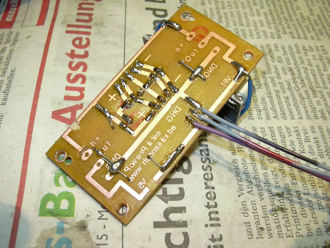
The soldered lines go to the locomotive speed controller. For batteries, the charging socket, battery alarm and battery switch are connectors soldered in. The wiring of the switching regulators was improvised.
The step-up switching regulator can be seen in the background, with the connector for battery alarm (left), charging socket (right), battery cells (in between) and battery switch (in front, black). The output lines to the locomotive controller are soldered under the circuit board, they are plugged into the locomotive controller.
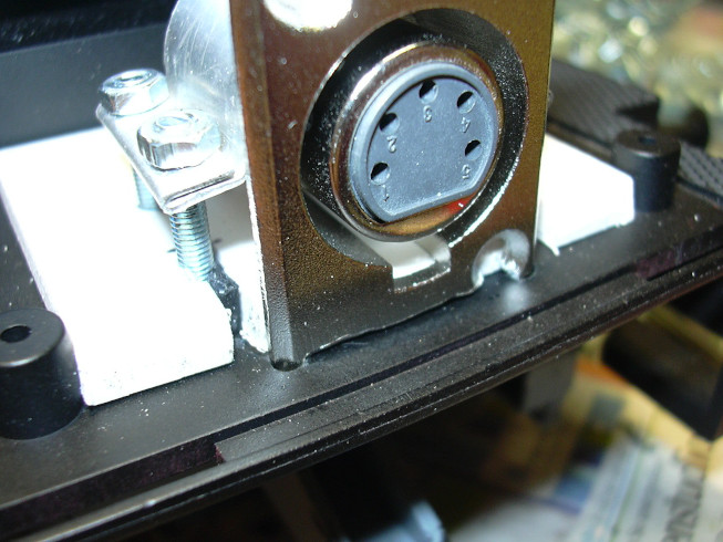
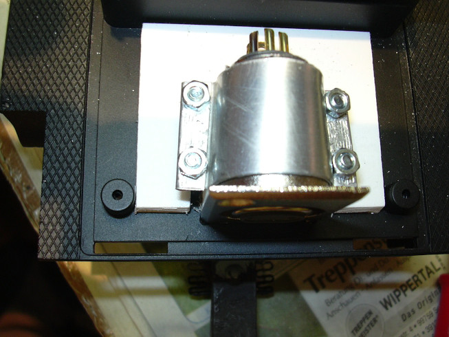
...was attached to the frame with a clamp and an intermediate plate assembled. At the lower edge of the flange, some material has been flexed off, so that two pins remained that reach into holes in the frame and secure the socket against shifting.
... and cut a plate made of ABS and drilled the 20mm hole for the charging plug.
both switching regulators at the outputs donated additional electrolytic capacitors, but this did not bring real success.

The interferences in the microcontroller could only be caused by a separate Ground line to the PWM-FET and some additional capacitors (Kerkos and electrolytic capacitors) can be eliminated directly on the speed controller board.
So that when you remove and put on the locomotive housing, the interior lining can remain screwed on, the connections for headlights and Interior lighting (pluggable) extended and the new pin headers to the walls of the interior cladding mounted.

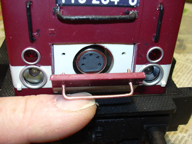
This was made from copper wire and is now waiting for black colour. The handle bar was pressed into the door and glued. The ends of the handle bar protrude from the back of the plate, so that when placing the door into the holes in the ABS plate and thereby the fix the position of the door.
and then closes it at the top. The magnets then hold the flap shut securely.