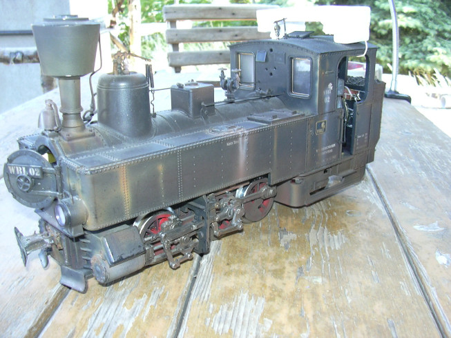
Conversion of a U to battery operation and radio remote control using Planet5B (2,4 GHz) |
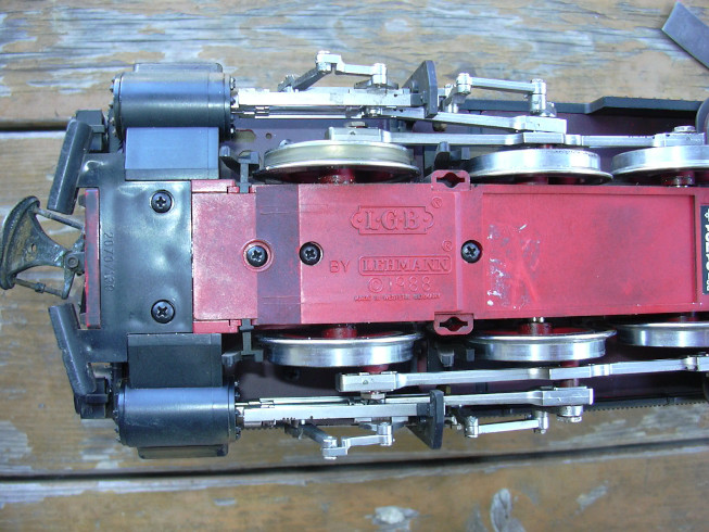
Actually, I wanted to remove all sliders non-destructively, but the previous owner meant well and all pantographs with thick Wire soldered together well.
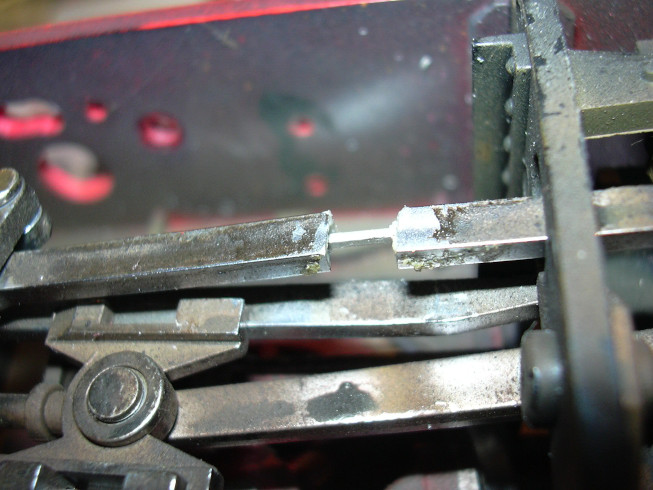
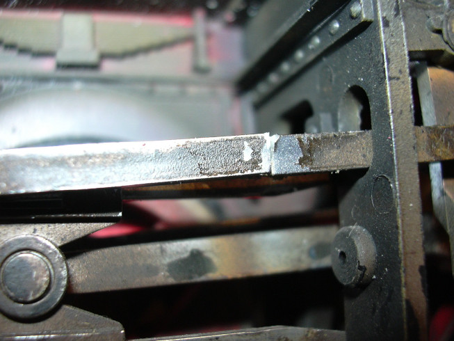
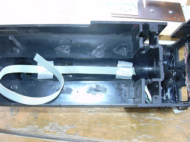
You can see it better here. It was difficult to unsolder the wires without scorching the plastic of the gearbox housing. I did not succeed in removing the solder from the sleeves. So I wasn't able to push the sleeves outwards through the holes. If the charcoal pins were stuck due to the crimped sleeves, they broke during the attempt of removing. Well, I didn't like that, but what should you do to do?
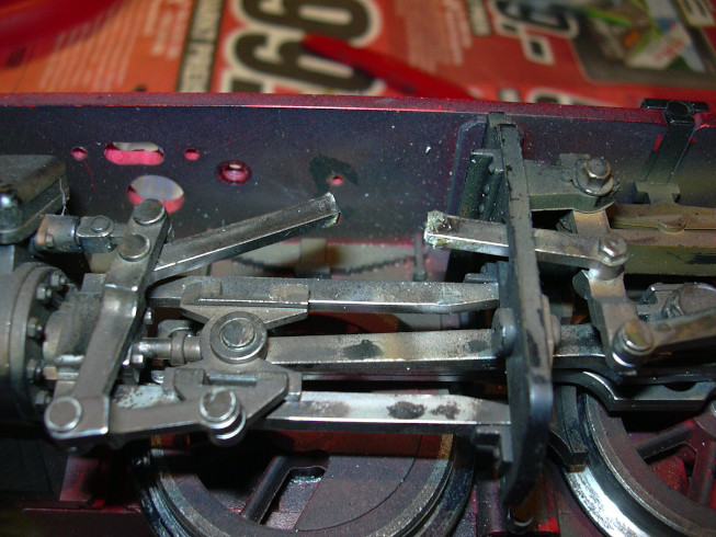
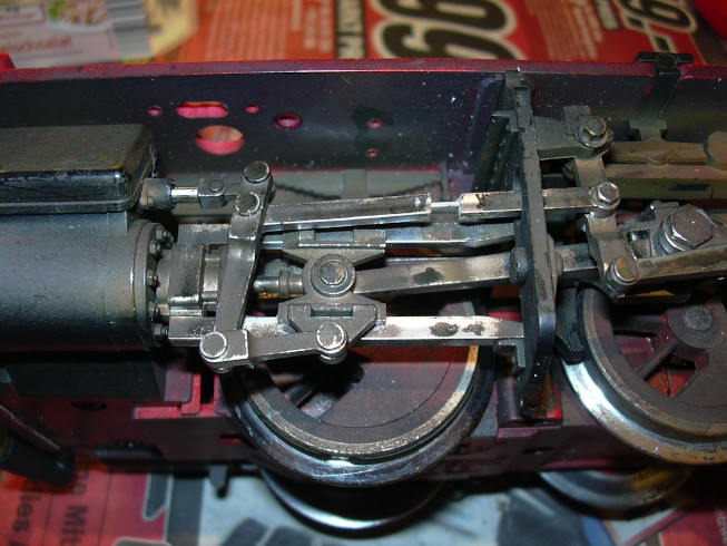
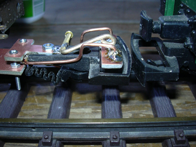
A rod in the control system was broken and it was broken by the previous owner had been glued unsuccessfully. With these loosely hanging I didn’t want to put the locomotive into operation.
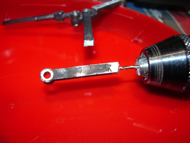
Most adhesives refuse to work if there are rests of former glue attemmpts. So I wanted to avoid pure gluing. The bone (uh, the rod) had to be mended. You could "seem" as if you had broken your leg, that would be seen a bit stupid. So I have both ends of the break as with bone surgeons drilled, first the loose, so what one could unscrew, ...
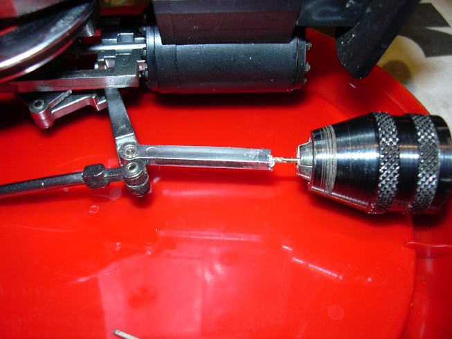
... then the end that was riveted to the rest of the linkage, ...
... and a square pin from a pin header (contact material) used, just like the bone doctors with thigh bones or do something similar ...
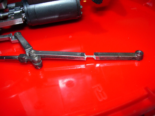
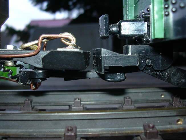
Now the linkage can be reinstalled ...
... to see a little closer here ...
... and after adding some rosin solution push together. The rosin solution ensures that the pen after is difficult to move after it has dried out. Well, exactly I didn't hit it, but if there is still some patina on it, then you have to look very closely to find it.
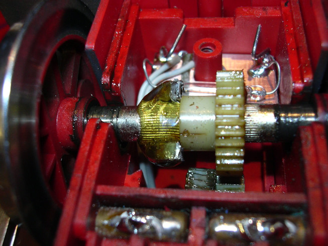
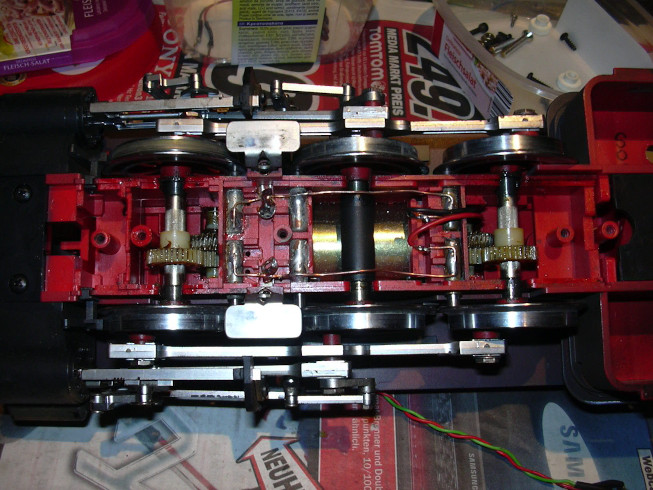
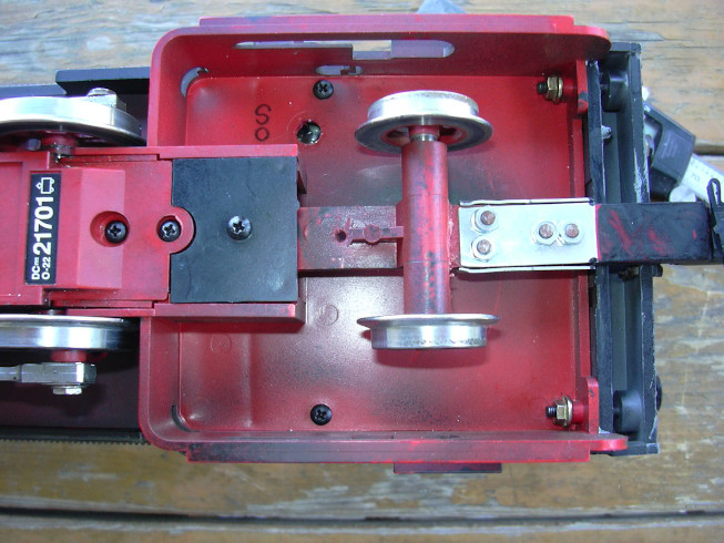
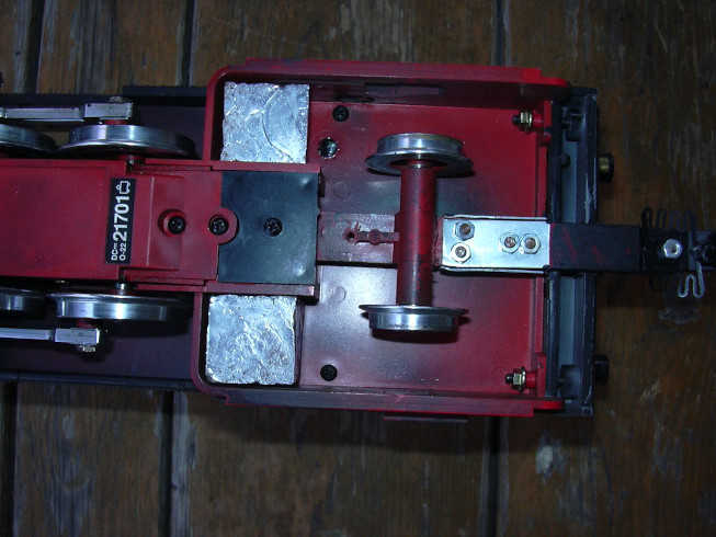
The axles of some locomotives are made of non-magnetic stainless steel. The axles of this locomotive are made of normal steel, so magnetic. So a neodymium magnet was split with a pair of nippers and (initially only due to the magnetic force) at two opposite points on the axis glued.
Then this place was fixed with an adhesive and the gears run at low speed so that the adhesive does not drips due to gravity and causes damage.
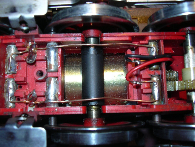
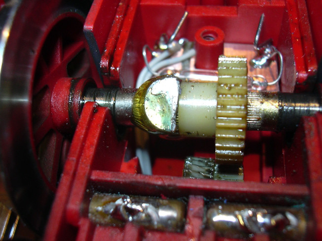
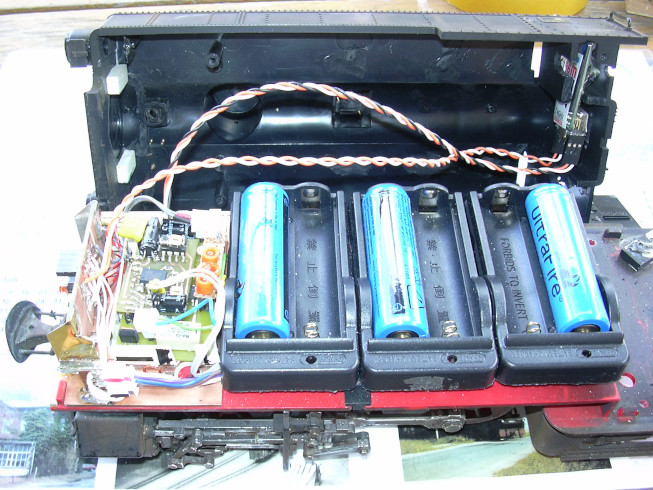
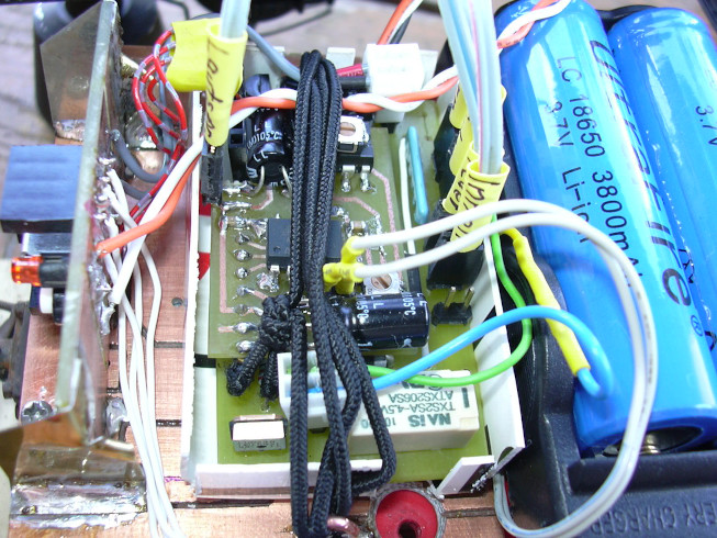
Here from the other point of view, the reed contact became consciously something long-wire mounted so that it can be adjusted with the help of the wires. The other bent thick wires are used for mechanical fixation of the circuit board. The gear cover presses the circuit board in over it a fixed position.
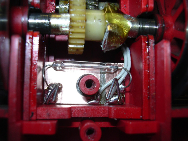
Again from a slightly different point of view.
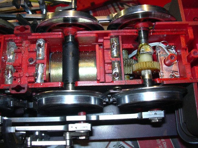
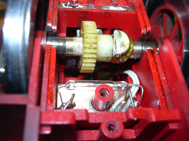
The gearbox before closing the cover. It still runs at about one revolution per second. The gearbox before closing the cover. It still runs at about one revolution per second.
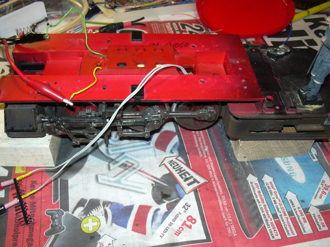
Now the chassis stands on trestles and runs and runs so that the glue does no harm. To do this, the motor is to the left of the power supply unit fed in. The gray cable on the right comes from the reed contact of the Wheel sensor. There is a beeping continuity tester for testing connected.
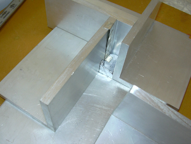
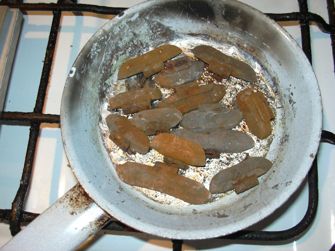
The open form. the metal strip served as a measuring stick for the filling level.
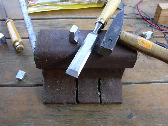
The sprues were then knocked off with a sharp blade. A piece of railroad track serves as an anvil.

First a cylinder box was filled with ballast
And then the other cylinder box.

Blanks for the sides, the right piece was due to a better one Idea melted down again. The chopped off parts of the blanks, of course too.
The side parts are cut and inserted.
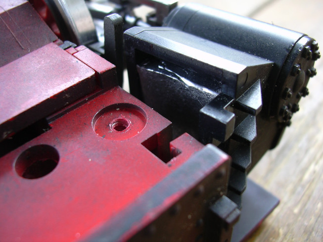
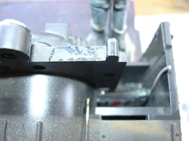
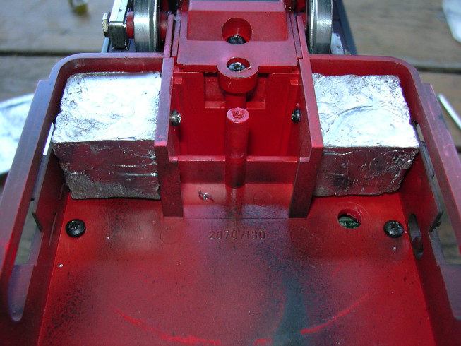
Da soll nun dieser Klotz dazwischen. Die vorderen Nuten sind nötig, da die Schraubenspitzen der Kupplung im Weg sind.
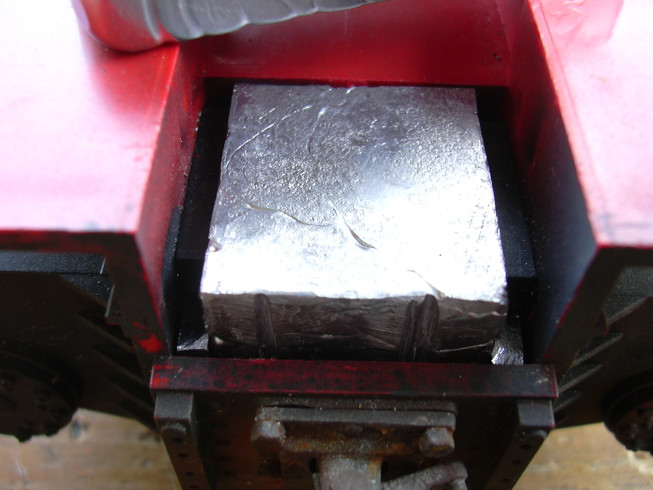
Now the block is in. At the front on the sides you can see the side parts that fill the space between the cylinder locking lugs.
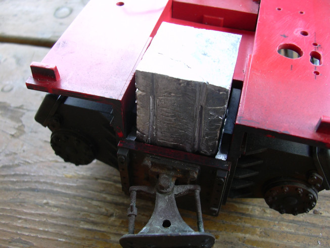
The upper part was re-cast and cut a bit.
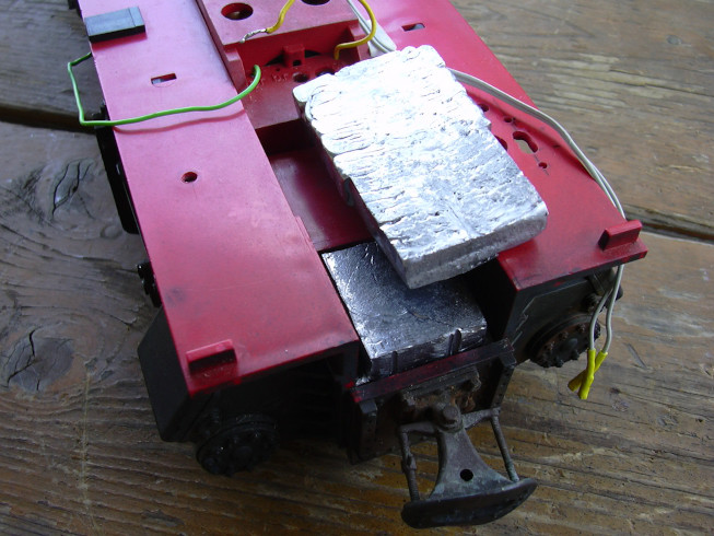
Here again before inserting ...

...and now it's in there too. Later the parts were with something contact adhesive UHU fixed, but this only happened after taking photos.
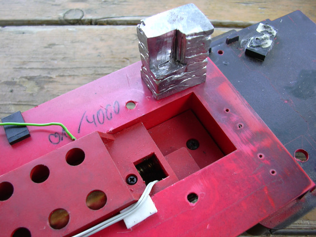
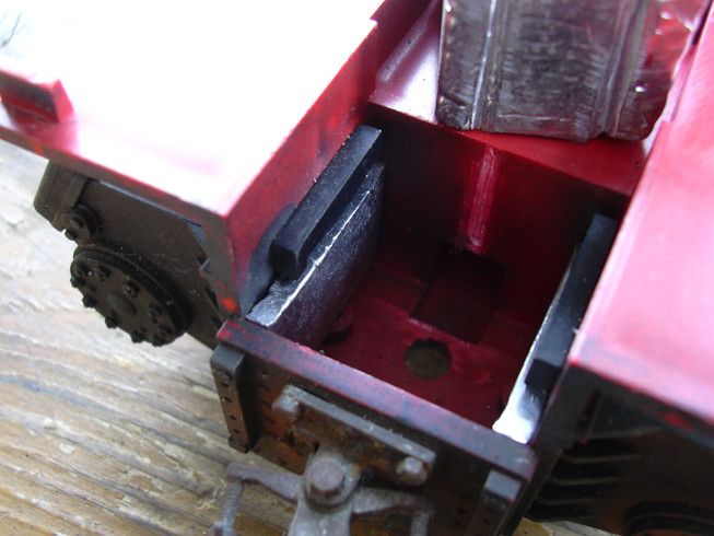
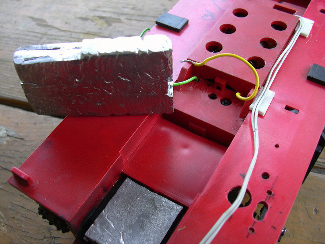
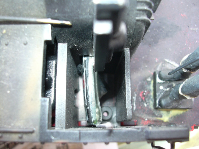
For the "hole" behind the gearbox a weight was also cast, a corner worked out ...
... and inserted. The height is by design as the battery chamber is arranged a little higher due to the high middle section of the gearbox.
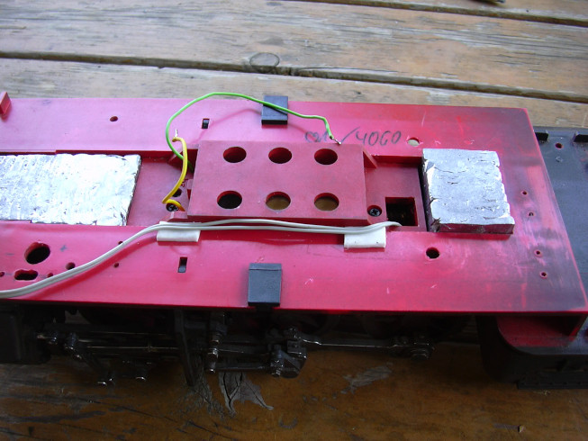
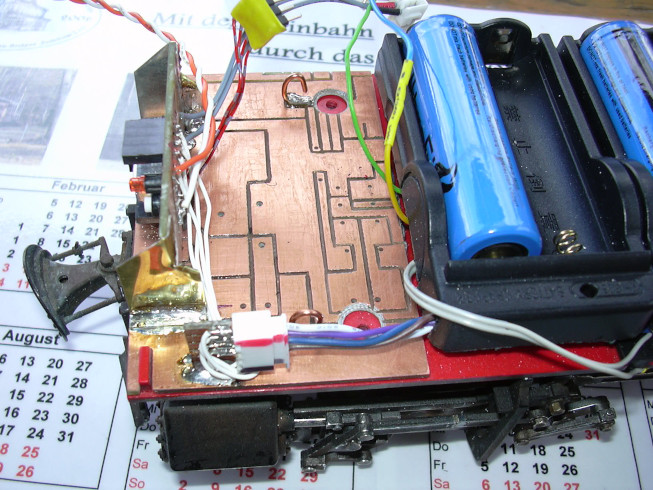
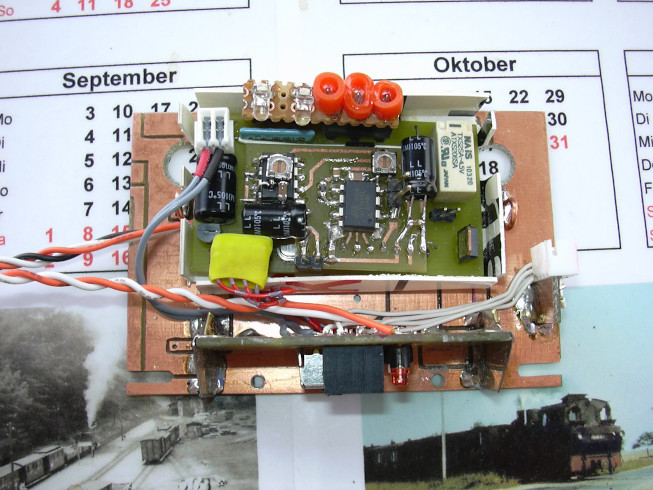
A piece of circuit board material that has already been milled and was drilled for some purpose, but was never equipped, was used as a carrier plate. Then the one-sided (flexed) control board attached. A piece of double sided circuit board material carries the connector for the battery.

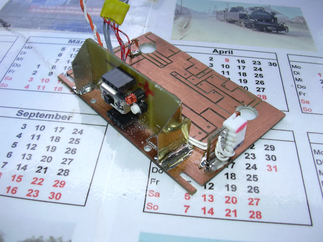
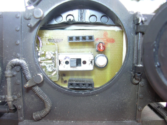
The operating side ... Above is the charging socket, in such a way that the charger's cell voltmeter can be read from above (see image section below left). In the middle is the battery switch, right next to it the button and LED for binding of the radio receiver. Below the PC interface is arranged.
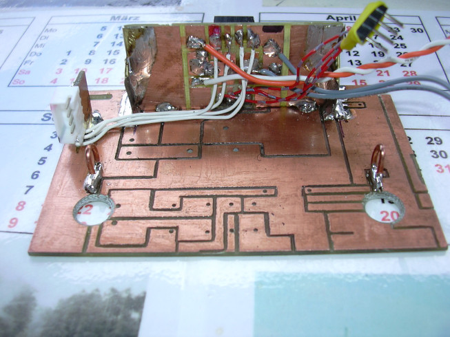
The subframe seen from behind ... The strings clockwise: PC interface (4-pin plug), radio receiver (LED, button), battery connection for locomotive speed controller (gray), battery connection (white). There are two more above the bores (the attachment of the boiler) two hooks for the eventual hanging of a rubber ring that holds the electronics.
The operating side ... Through the two holes in the base plate the entire subframe is screwed to the locomotive frame. Before the final When reassembling, the locomotive is blown out again with compressed air.
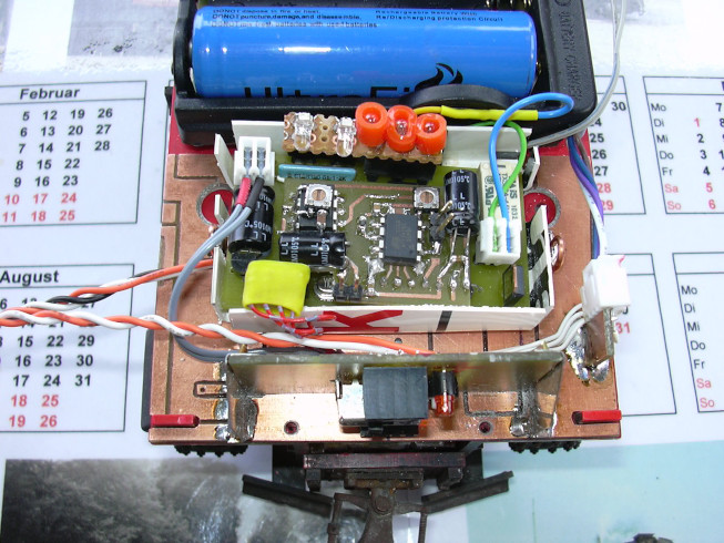
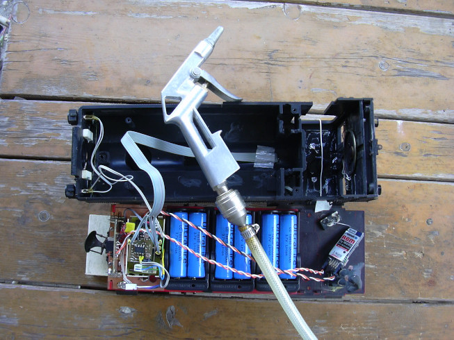
Subframe with connected battery. For the time being, only 3 cells are used.
View into the smoke chamber.
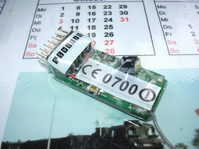
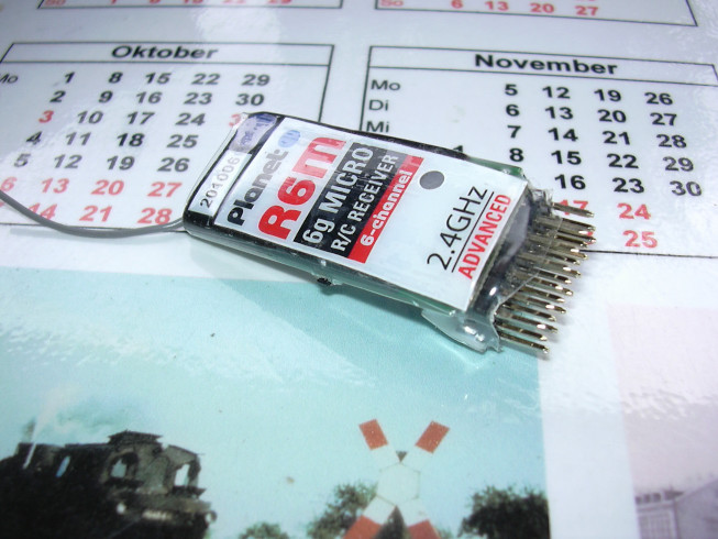
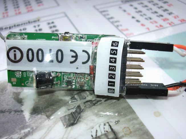
The radio receiver got a slimming diet. The printed housing parts with shrink-wrapped, which are unique Identification (e.g. by authorities) are necessary.
The other side of the radio receiver. A hole was cut in the shrink tube on the button.
The two red wires on the left are for connecting the external control unit (button, LED). To the right connection (battery connection) lead the 3 diodes that generate the impulses of channels 1, 3 and 5 sum up. This saves an external circuit board on the connector of the receiver.
1 mm PVC was used to insulate the locomotive speed controller board (old train route sign of the DB) made a "bed". This is now done with carpet tape attached to the base plate.
So tight...
And now with content too.
Again from a different point of view. The test plug with the LEDs and light bulbs is still attached to the light and function connections.
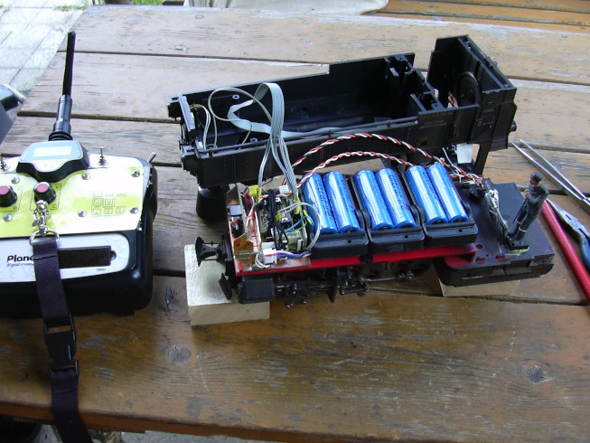
The subframe with content in the locomotive. Electricity (top left), motor (right) and PC interface (bottom left) are already connected.
The modified receiver will now have a 3-pin connector (below) connected because the diodes to combine the channel impulses are in the receiver, the sum signal is on so far unused pulse pin of the battery connection is available. The upper Connector (channel 6) is used to connect (external) buttons and LED.
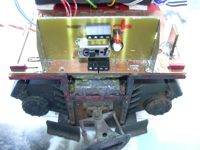
Since there was no more space in the front, the radio receiver was in the fire box banished. For this purpose, a slot was made in the housing bulkhead with the 12V-Flex incised.
View from the other side. The wires are then in the vessel above the batteries misplaced. Then there are also the wires for light and speakers too.
This picture was supposed to show the receiver from above, but the autofocus preferred the dashboard of the heater.
The autofocus didn't really work here either. You can still see the receiver, albeit a bit blurred.
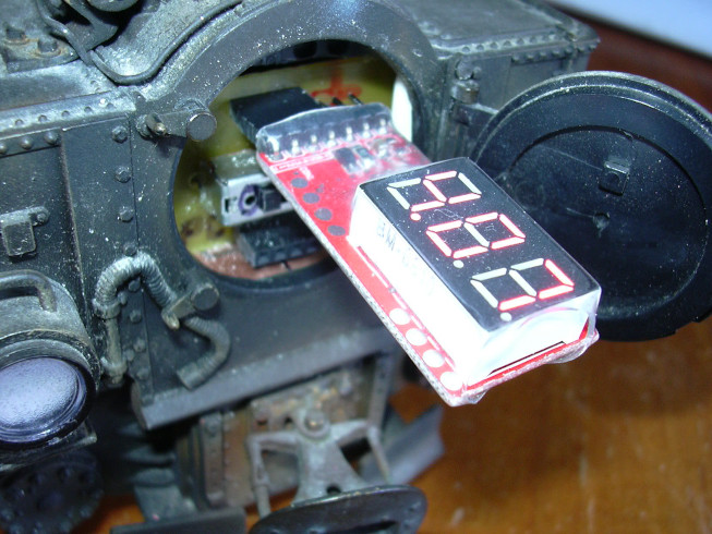
A battery tester to check the space available (it just shows 4.07V on). The connection of the charger should therefore not pose any problems.
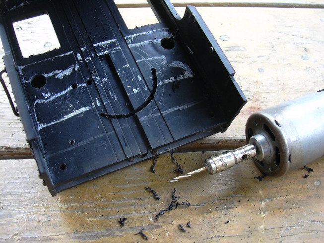
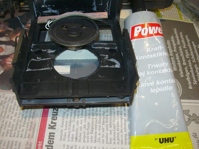
The outer pencil line (circle) is around the speaker been drawn. The inner circle was hand drawn, taking me the meanwhile somewhat aging sense of proportion deceives me again.
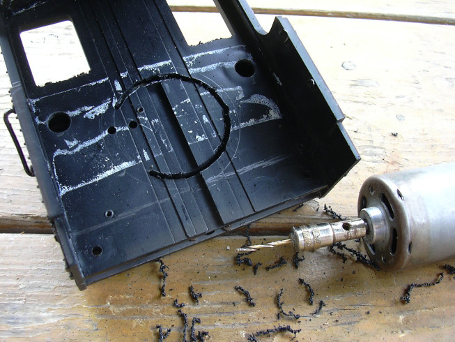
Now the drill motor needs the second short break. Milling doesn't leave him indifferent.

Puuuhhhh, done, where is the paper ... - Uhh, that was think another construction site ...
Of course the hole is too small, a sense of proportion like a dead pig ...
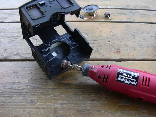
So "heavy equipment" has to be used.
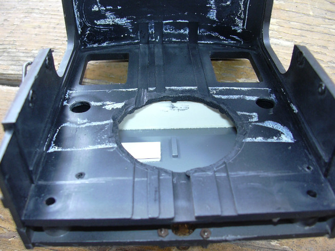
The hole has been enlarged and chamfered so that the loudspeaker can sink in a little deeper.
The first thought was to lead the wires out upwards, but this was rejected again.
Since soldering points are also required for the LEDs of the lamp a piece of circuit board material had to be abused.
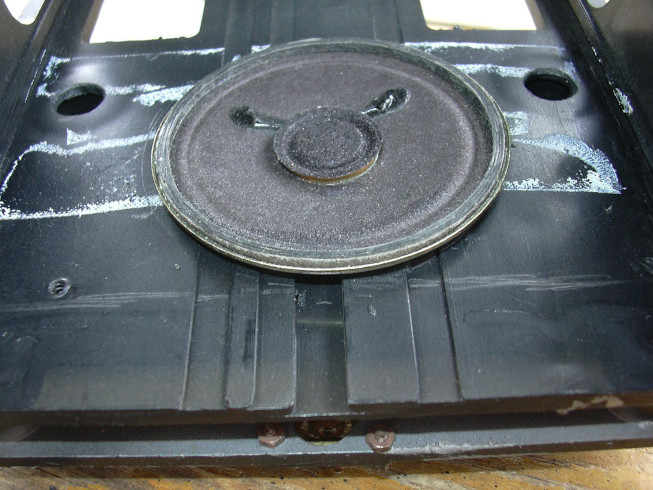
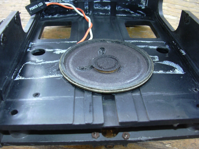
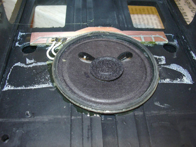
That's how it should be.
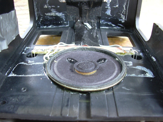
Now the concentrated power of UHU has to work, but not according to regulations as a contact adhesive, but as a permanently elastic sealant (i.e. without Pre-drying as with rubber solution). This is intended to enable later replacement of the Make the speaker easier.
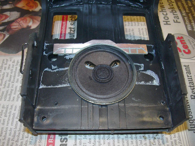
So, firm ... But only when the glue is firm. That's why I have now some time to look at the photos, comment on and the website to update.
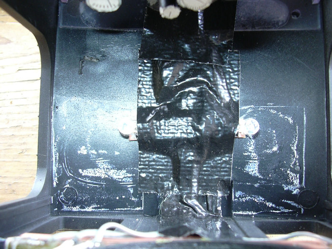
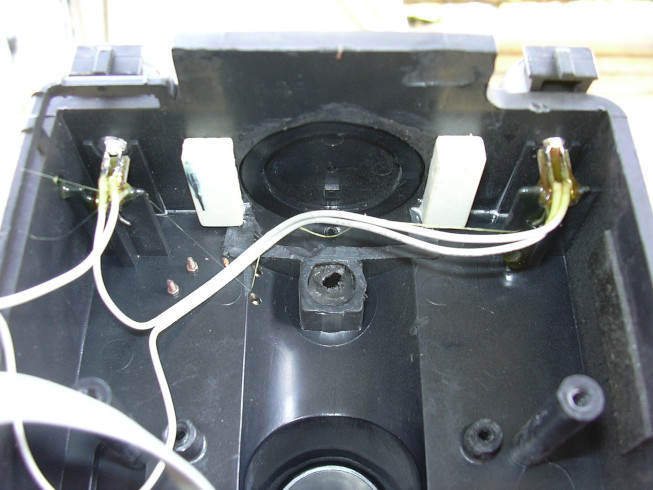
Loudspeakers and rear headlights are connected, the "wiring harness" is masked with black textile tape.
There is also a carrier for two lighting LEDs in the roof.
In order to bring the wiring harness to the front in an uncomplicated manner, the boiler drilled. A harness of it ends up in the empty space in front of the train driver (chamber at the bottom right), maybe someone can do that later fire imitation (flickering light) can be connected. But this is still the case not designed and built.
Now the locomotive first had to fight a hurricane. But it survived it.
The front headlights are now in there too. They were fixed with contact adhesive UHU.
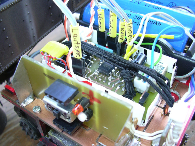
The promised rubber strip fixes the electronics. The plugs have been labeled.
Electronics with cables and rubber strips from a slightly different point of view.
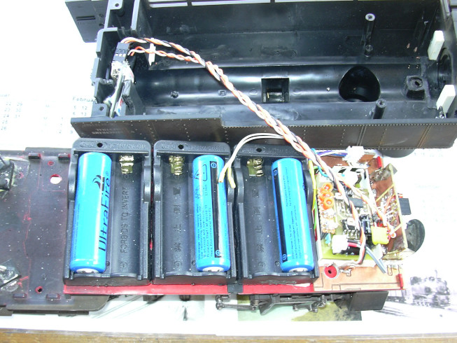
Now all 6 battery cells are also included. There is another test run.
The thing is closed, but not screwed yet.
Again from a different point of view during the test run.
Now it is screwed on and the barrel axle is reassembled.
It is also screwed in at the front, but the lower screw is hidden in the shade.
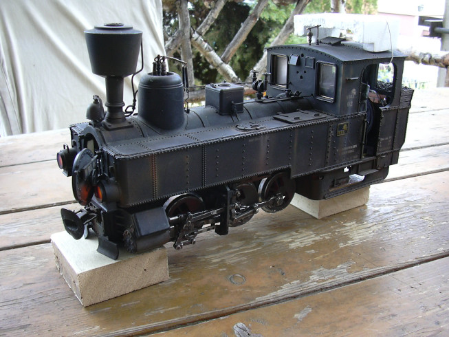
It looks a bit scruffy, I'm wondering whether I shouldn't Pour black nitro lacquer into the spray gun and something over the Inject rust over it ... - But first, the rear ballast has to be poured and installed.
A new cast is being prepared.
The blocks are fastened from the inside with screws.
Actually, I wanted to pour a thin plate to cover the area should fill out under the Bissel frame, but several attempts were made next to it, because the shape removes heat from the lead so quickly that thin casts become crooked and creepy. So it stays with these for the time being both weights.
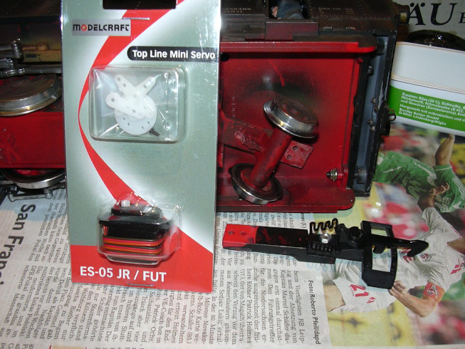
The round has to go into the square ... Uh, the servo has to go to the trailer.
So much in advance: That was left ...
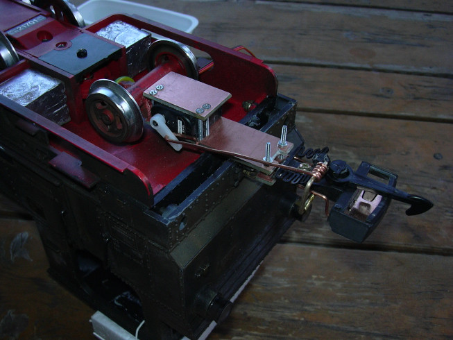
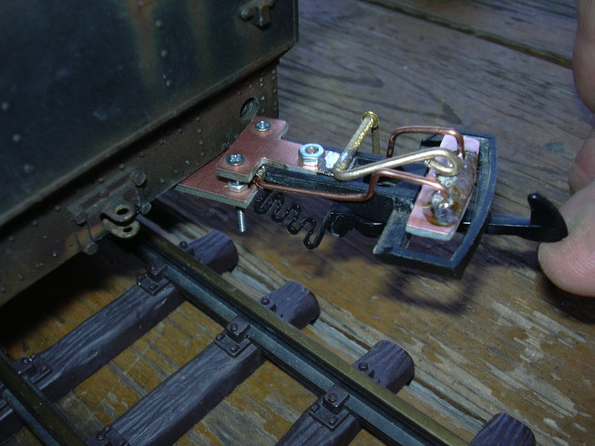
And this is how it looks from afar, a bit gloomy, but it was already late ... A strip of somewhat thicker epoxy circuit board material was attached to the trailer, which protrudes from the rear of the locomotive.
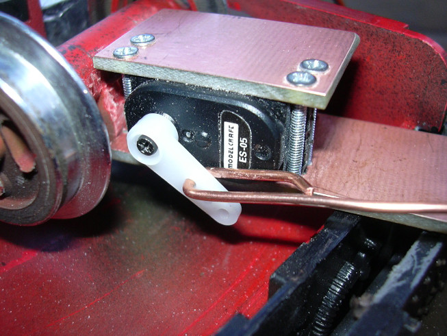
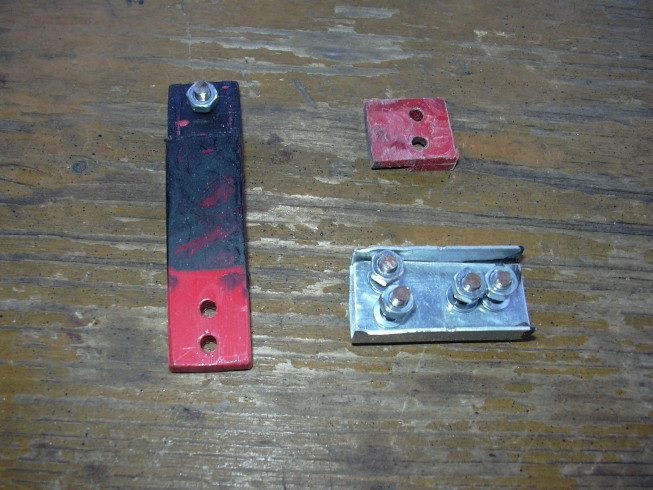
the servo was attached to it with a second plate and 4 M2 screws attached. The power transmission to the release plate takes over something copper wire with a diameter of 1.5 mm (NYA 1.5 qmm), which is used in mine single cell Stainz used 0.4mm steel wire turned out to be too weak. Because the original LGB clutch spring needs a lot strength to overcome.
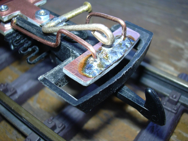
The push-out plate is movably suspended with 1.5 copper wire. you the coupling hook is lifted by the spring force. For the push-out lever was used brass, copper wire turned out to be too soft. 2mm brazing wire with fine emery cloth was cut to about 1.7mm sanded off so that it was used as a warehouse brass hollow rivet fits. The connection of the coupling carrier with the servo carrier was initially made with M2 screws. I will do this in the Replace with M3 or M4 (if there is space) in the next few days.
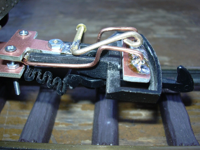
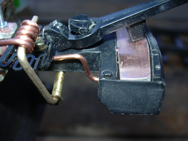
Here you can see that the full length of the trailer is necessary, because the coupling sits above the lower edge of the housing.
The same on the other stop. A shorter attachment was not possible, because the coupling carrier must be above the coupling, so that the spring remains movable. And unfortunately the spring also needs all sorts of space.
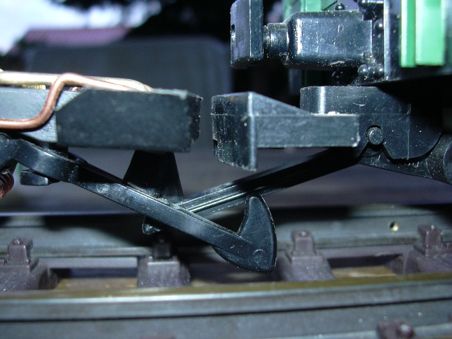
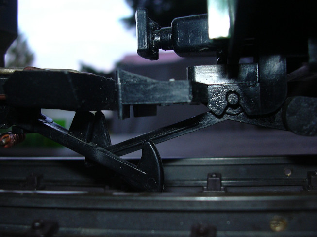
The push-out plate can be wired at the bends of its copper wire suspension can be adjusted. The expressive power is working over the brass lever on the center of the plate. In the engaged state there is some space between the ejector lever and the plate.
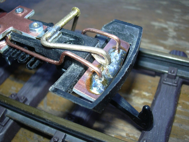
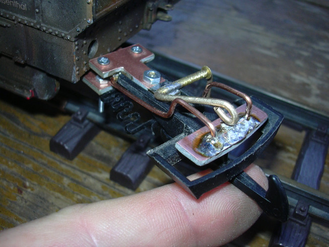
In the uncoupled state, the lever pushes the plate so far below that the coupling hooks Find no longer hold in the coupling bracket.
Disengaged view from below. The connection of the pull rod on the ejector lever is also clearly visible.
First test with a two-axle luggage car, coupled ...
Slightly different view, engaged ...
Disengaged ...
Slightly different view, the hook of the luggage car is barely free ...
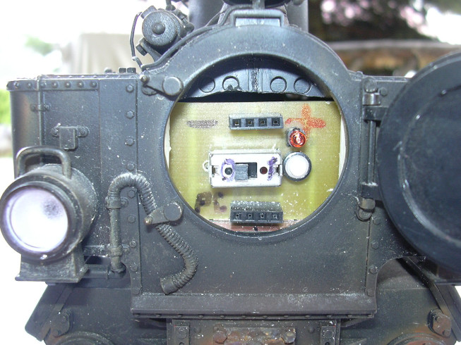
The servo positions are adjusted using the two potentiometers of the sservo control board, which are easily accessible in the smoke chamber (left next to the switch).
To secure the power supply to the servo, the power supply was used of the entire electronics changed. Plus the third cell (11.1V) will now only used for engine and light. Radio receiver, cruise control, sound generation and amplification are now carried out via the tapping the first cell. This saves the voltage regulator (here only bridged). The disadvantage that the lower battery cell through the base load the electronics are subjected to higher loads is actually an advantage, because as a result, the lower cell is always empty first and leads due to the undervoltage shutdown (reset of the microcontroller at below 2.7V) the speed controller to log out the locomotive before the upper cells are critical be discharged.
The software of the Lokomoteufelchen speed controller has also been changed. The operation of the switching functions has been improved. Here first only a short list, an exact description can be found at Opportunity on a separate page.