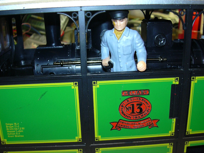
Conversion of the LGB tramway steam locomotive "Elias" to battery operation with RC control ... |
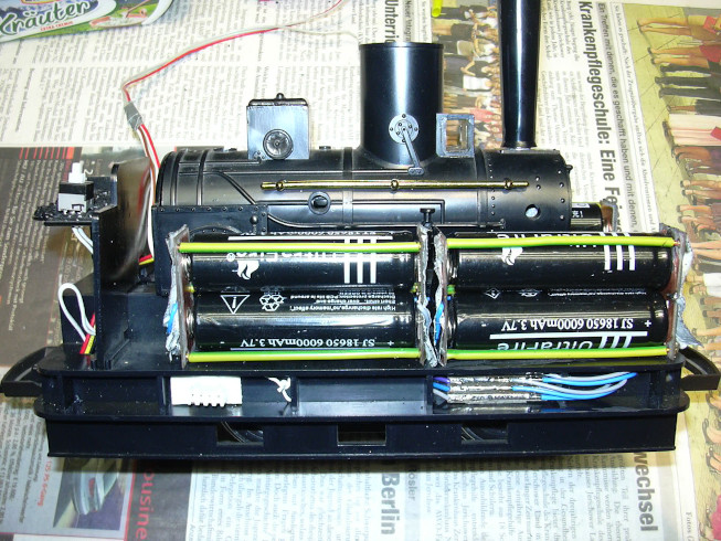
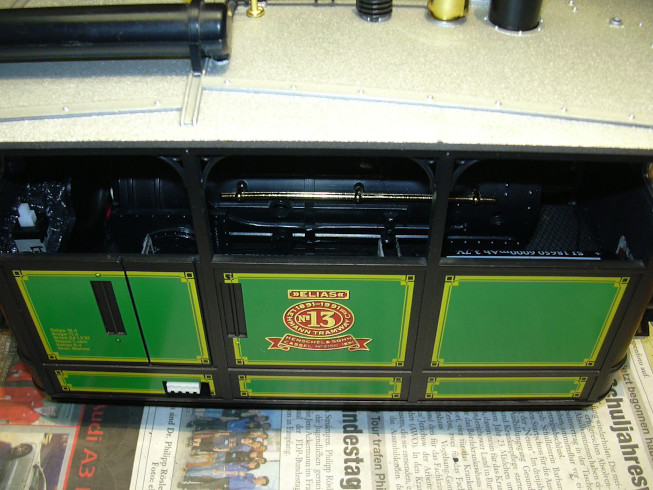
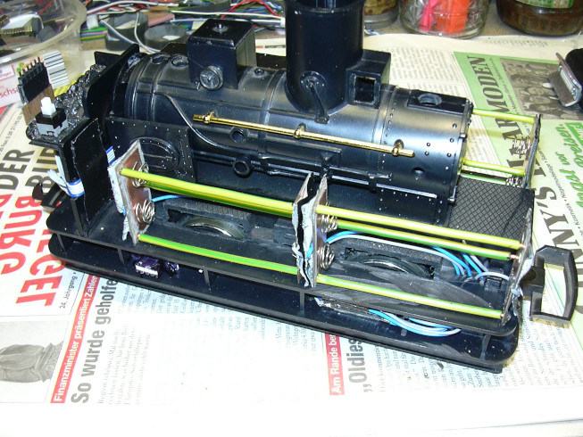
Since the space for fixtures in the locomotive is smaller than previously assumed, some components had to be placed under the frame.
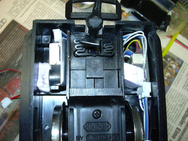
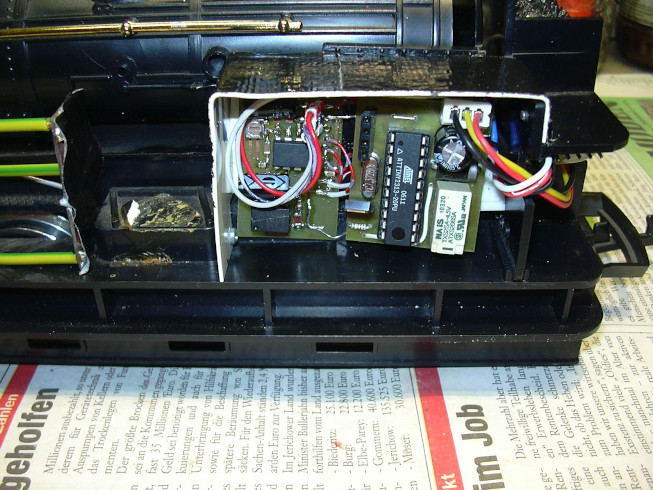
An adjustable battery alarm module is placed at the top left. This needs all connections of the battery (balancer connections), because each cell is checked individually for undervoltage. To avoid that the locomotive does not suck the battery empty, the battery must be switched off at all poles simuultanously. For this purpose a relay module was used, this one can be seen on the right in the picture above. The battery switch puts the first one on Tapping of the battery (4 V) on the relay coil and electronics, the relay then switches the 8 V of the second tap to the alarm module and the 12 V of the third cell on the alarm module and the power section of the Speed controller.
In the top center you can see the four-pole battery cable, the one on the left the relay board is supplied with power via the connector.
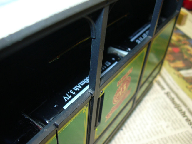
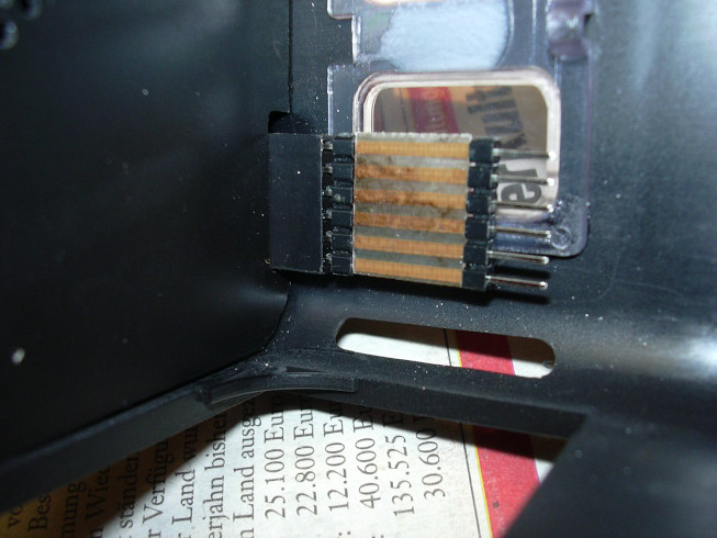
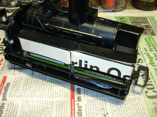
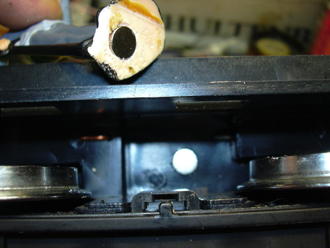
In the top right corner you can see the battery cables of the individual cells on the way to the collection point , which can be seen in the frame at the bottom right in the next picture.
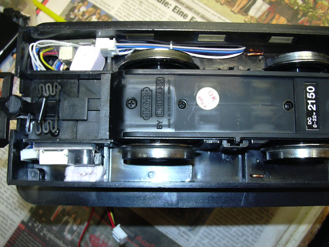
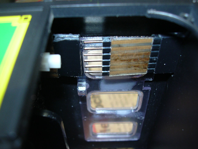
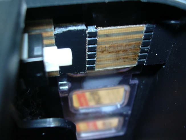
This is a piece of circuit board with 4 strips coming from the right the single cells are connected and to the left that (for all mine three-cell locomotive conversions common) leads out four-wire battery cables. On the left in the frame you can see (still completely white) the charging socket, its Route the cables to the relay board. Above the frame are 3 self-made battery chambers for 2 Li-ion cells connected in parallel the type 18650 mounted, 2 of them on this side, the third on the other side.
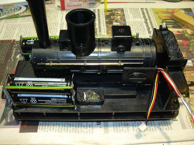
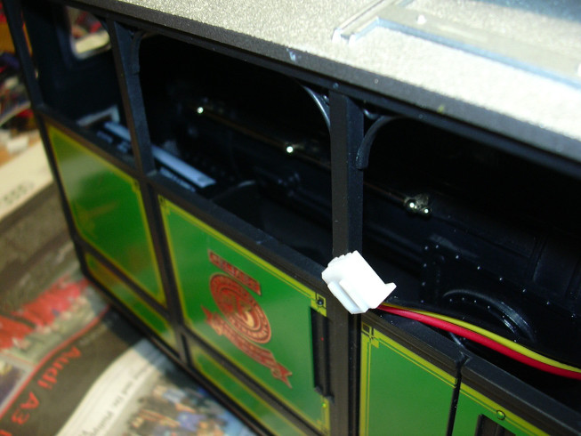
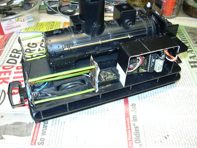
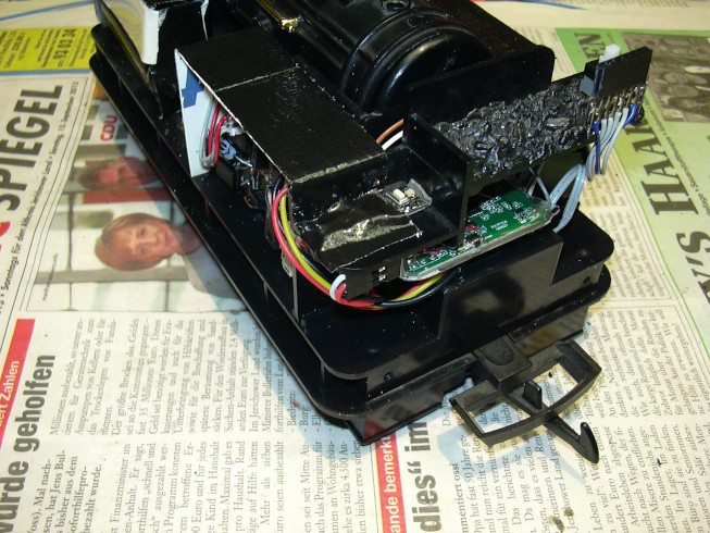
The battery switch can be seen on the top right of the coal box. The connections are made between the boiler and the coal box power supply (left three-core cable with 0 V, 4 V and 12 V), motor (right, brown and white) and hall sensor (right, ribbon red-gray-gray) upwards.
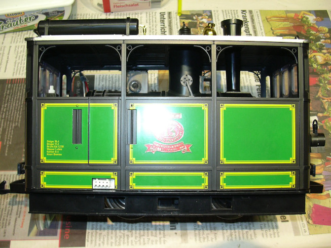
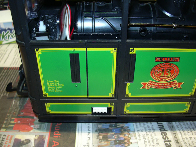
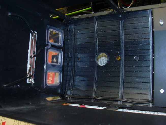
The battery switch (left in the window) is easily accessible, as is the charging socket (left in the step below the entrance).
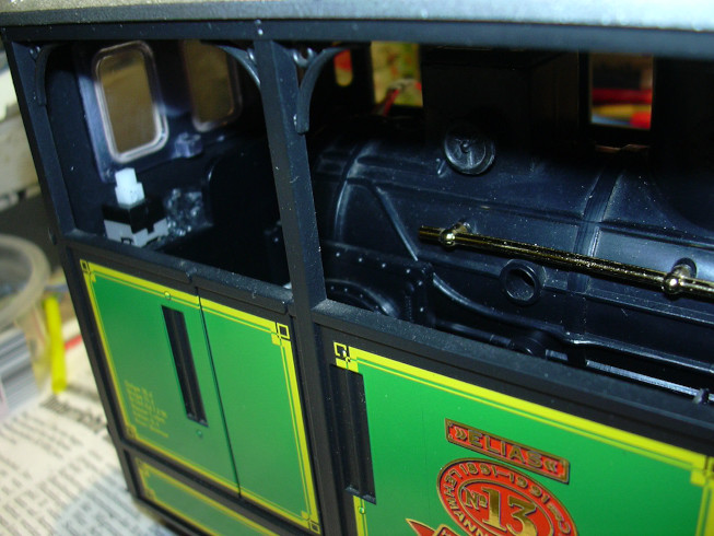
This is followed by glimpses from diagonally above to see to what extent the batteries disturb the overall picture.
This is the freshly painted false ceiling in poor light conditions.

It is used to hold a flat loudspeaker and two LEDs (interior lighting).
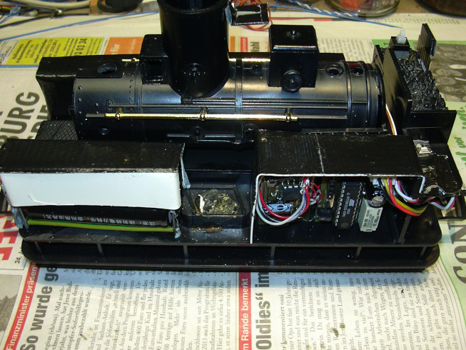
A "control cabinet" was built for the electronics:
On the left you can see the sound board (ATTiny85 / LM386) to which (above on the right on the left circuit board) the Hall sensor (placed in the gearbox) is connected via connector. On the right edge of the Sound modules are the connections to the locomotive speed controller (multifunctional speed controller with ATTiny2313, logic level power FET and Pole reversal relay, right board) and to the loudspeaker (gray wires) see.
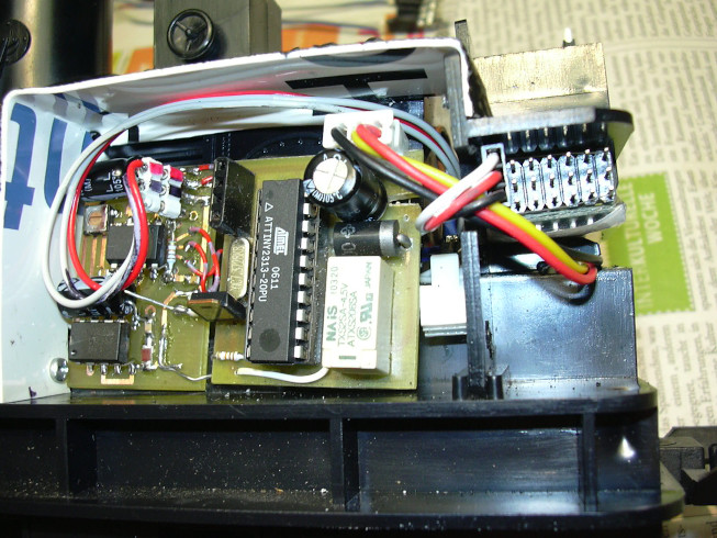
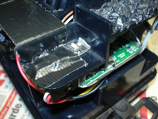
The power supply cable is on the top right of the locomotive controller board attached (ground, 4 V, 12 V). Top left (arranged vertically) is the socket for the RS232 connection. The PC can be connected here to parameterize the CVs of the locomotive speed controller, but also a additional module that implements additional functions. A cable leads to the right to the radio receiver, ...
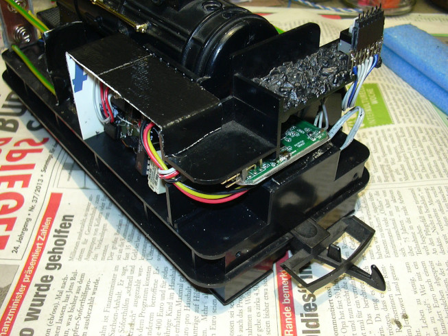
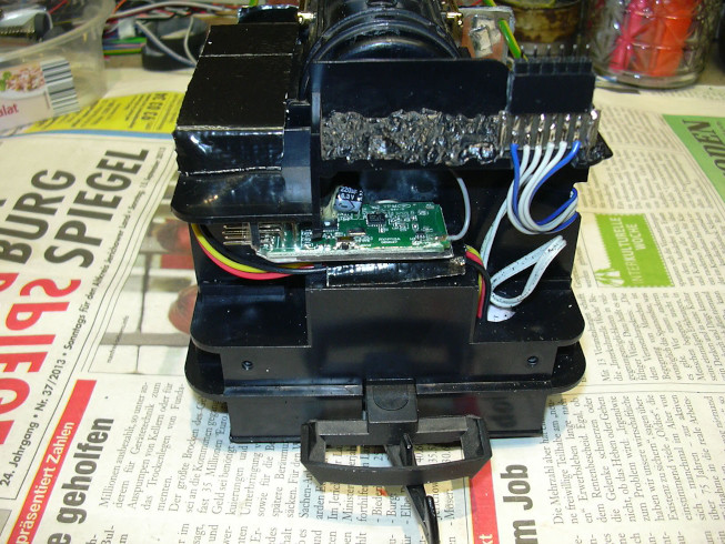
... which has found space under the coal box. Right on top of the Coal is the connector to the car body, via the front lighting, interior lighting and speakers can be connected. Bottom right is the cable entry from the relay board (black / red / yellow to locomotive controller and gray / gray to the switch).
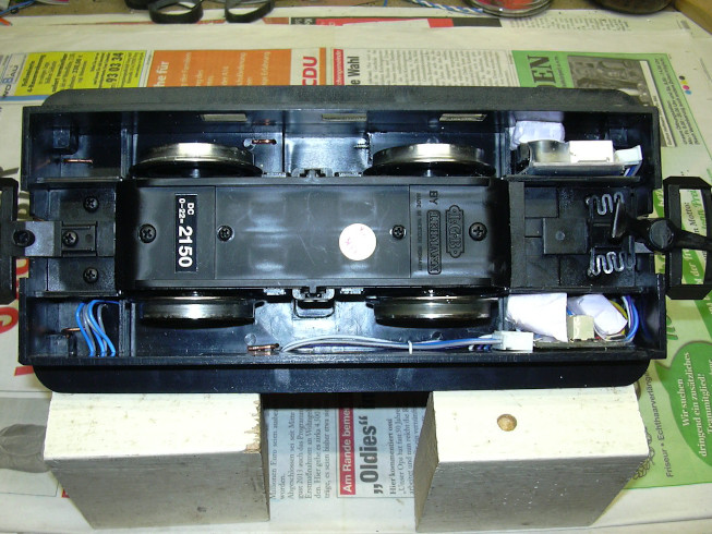
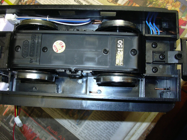
The bent copper wires are the fastening tabs for the Battery chambers. The battery cable was fixed with a wire clip, so that it cannot drag on the wheel. The boards on the right are with clamped styrodur blocks.
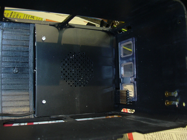
The false ceiling with loudspeaker and two LEDs (left) is with glued in double-sided tape. At the lower left corner of the Suspended ceiling leads the cable to the front lighting. On the right edge is the connector to the lower part of the locomotive can be seen.
On the front ...
... a circuit board for connecting the 3 front lamps is glued on. This was later covered with black textile tape.
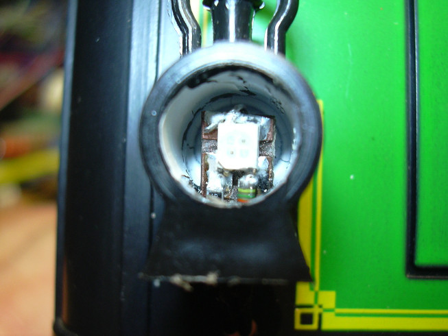
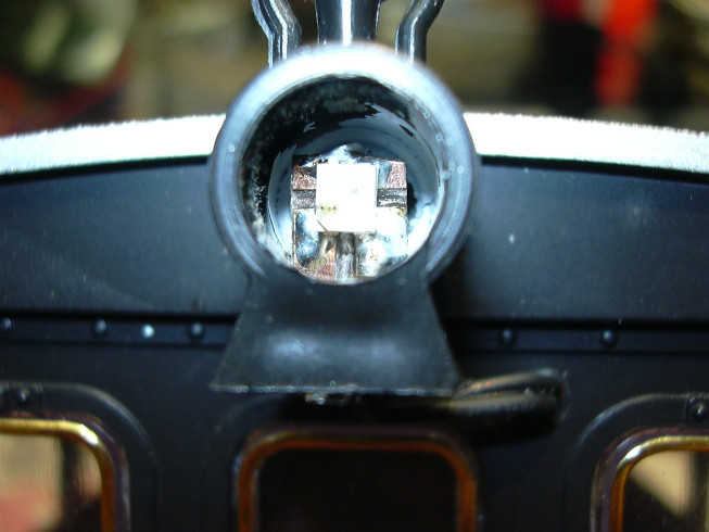
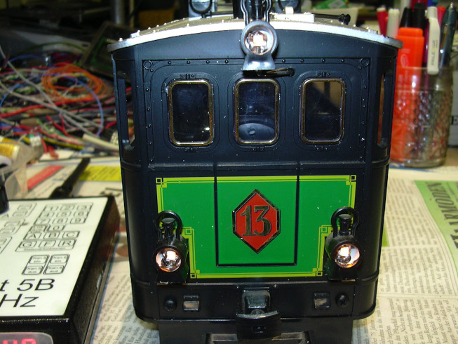
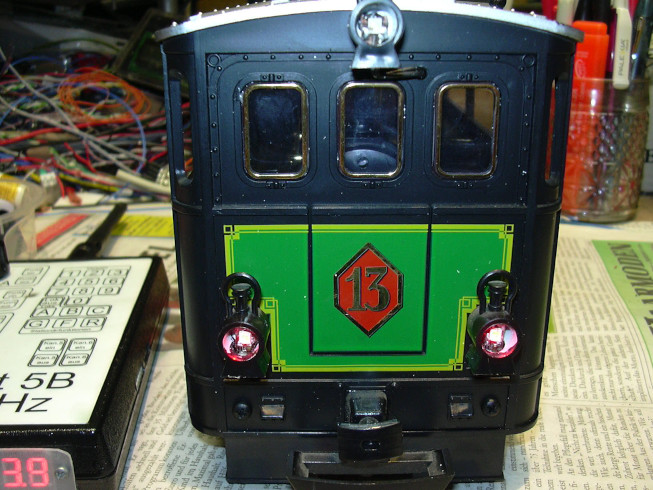
... two-colored SMD LEDs (red / yellow) are used that point to small PCB pieces were soldered, which also carry the SMD series resistors. Both LEDs are connected in antiparallel, which causes the color change polarity reversal enabled.
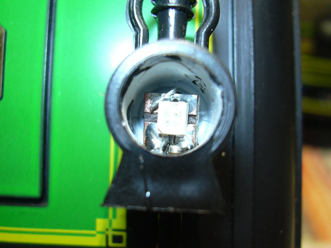
The resistor for the red LED was not fitted in the upper headlight.
... and put together.
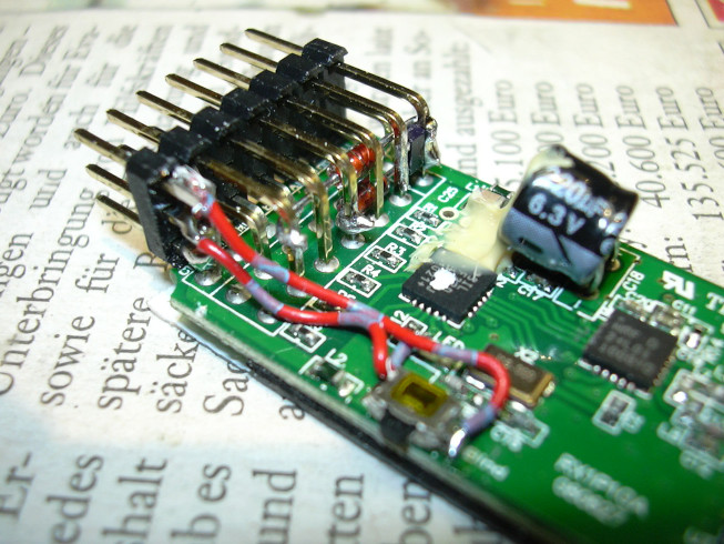
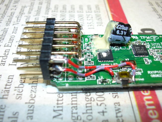
For this purpose, the two pins of the unused connection of channel 6 were removed for plus and impulse separated from the circuit board (pinched out) and using a piece of circuit board (3 solder pads) mechanically with the ground pin connected. These now free pins were connected by means of wire (red / blue-gray) Bind LED and bind button connected.
In the picture you can see how the impulse connections of channels 1, 3 and 5 too by means of diodes to the (originally open) pin of the Battery connection are summarized. This allows locomotive speed controller to read channels 1 to 5 via just one I / O line of the the microcontroller.
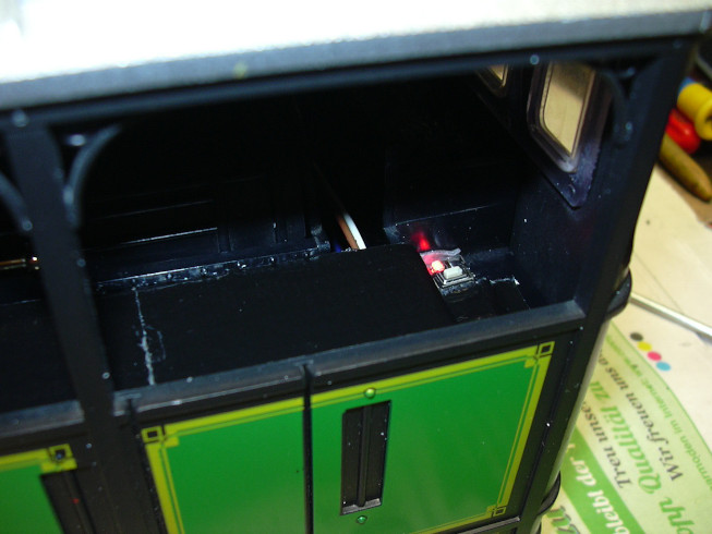
The external button / LED combination was above next to the coal box glued. There it is easily accessible, but still not excessive noticeable.
... and covered with black textile tape.
The owner can now place his beer boxes or flower boxes on it.
... is barely recognizable because of the camera's flash. You can see the red light a little better.
Now it remains steady fast and even rotatable in its place without hindering the opening of the locomotive.