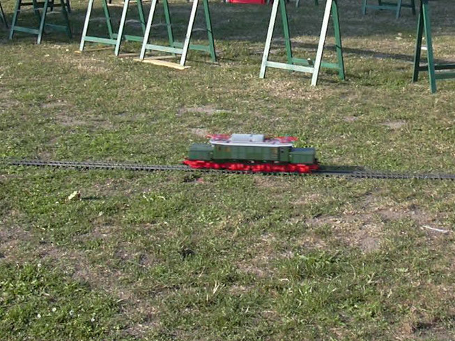
Reconstruction of a german electric loco Crocodile "E94" of PIKO being operated by battery pack and 2.4 GHz radio control |
After the E94 had some problems witth sticking slides in sswitches and skipping gears in the gearboxes, the decision was made to convert it to battery operation and RC control. Here is the good piece with the gearbox damaged after the last use with power supply by tracks:
The transmission problems later turned out to be consequential damage to the broken soldering points on the bogie connection cables due to the shrink tubing was only discovered on closer inspection. As a result, a drive occasionally failed, which was due to the self-locking gear (single geared scroll, in the event of a power supply failure strongly braking motors) led to overloading of the gears. There was occasionally the problem that the locomotive derailed in little radii, there the stems just didn't want to follow the curves. I suspected it was on the friction between the midframe and the front frame was the probable cause The real cause was found later. But it turned out not to be a good idea by a designer to use Garden railway locomotive equipped with rub smooth, greased plastic surfaces outdoors. It is inevitable that there will be gravel particles accumulating, scratching the surfaces and making the bogie hard to be moved. A couple of washers and bushings made of polyamide or Teflon and other case dimensions would be miraculous.
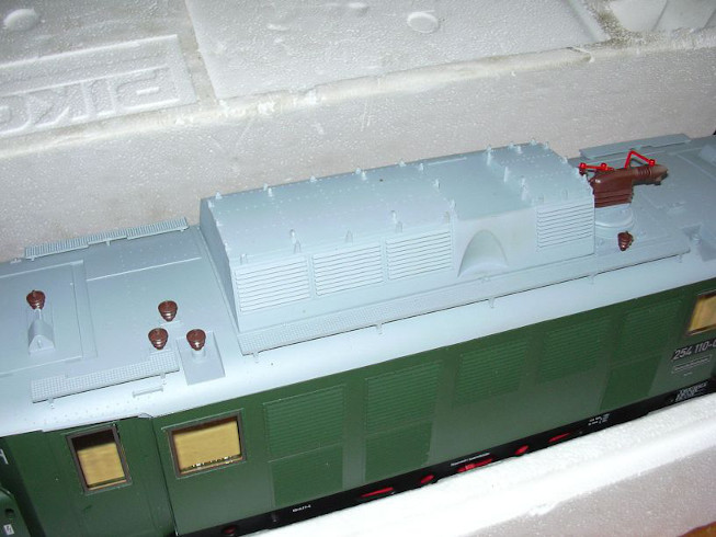
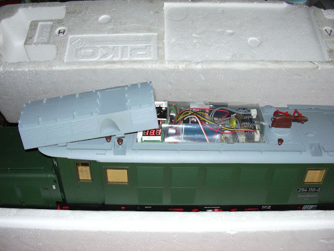
A view of the middle section of the locomotive, pantographs and roof cables have been dismantled not to damage them.

These four lithium iron phosphate batteries (3.3V / 10 Ah) should be installed. In order to avoid short circuits when testing the battery provided at first with secure connection cables and contacts being isolated. I had prejudices that the the high price of the battery cells would not be justified, but Uwe insisted to use them. In between I take it a little more easy, because the batteries hold on actually a twelve-hour driving day easily. And since then Battery undervoltage alarm module has been retrofitted, I don't have any more concerns, because the locomotive suggests a long time before deep discharge a rechargeable cell alarm.
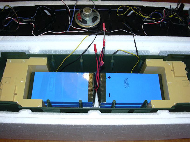
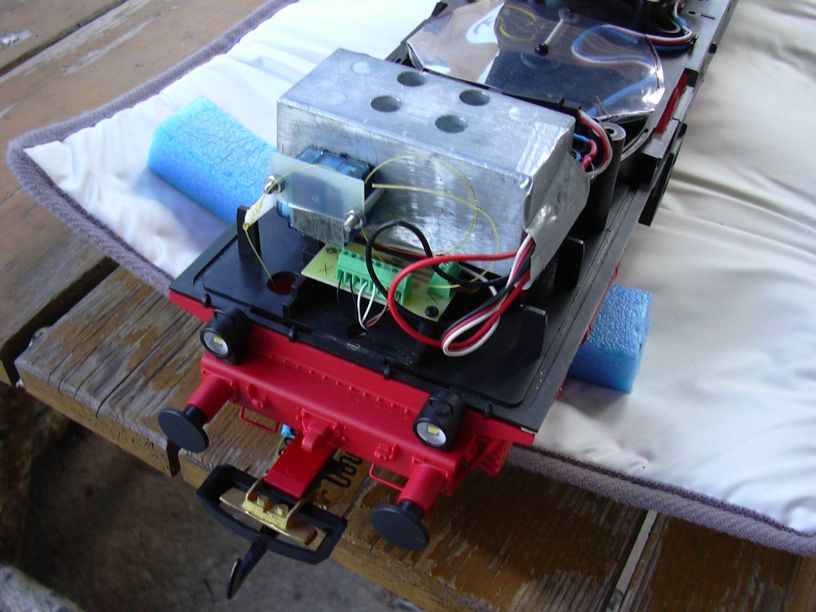
Here you can see a first fitting, the 4 cells just fit in, it but will be tight. But a good friend of mine always says: "tight is beeeeaaauuuutiful ...".

A subframe was made for the batteries, which is placed on the pin of the removed weights. Underneath there was loudspeaker being mounted. The side aluminum angles are used for the side Fixation of the battery cells and the attachment of strips over the Cells that serve as the chassis for the electronic components.
These cross supports were obstacles, they hhadd been quickly flexed.
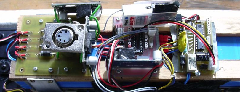
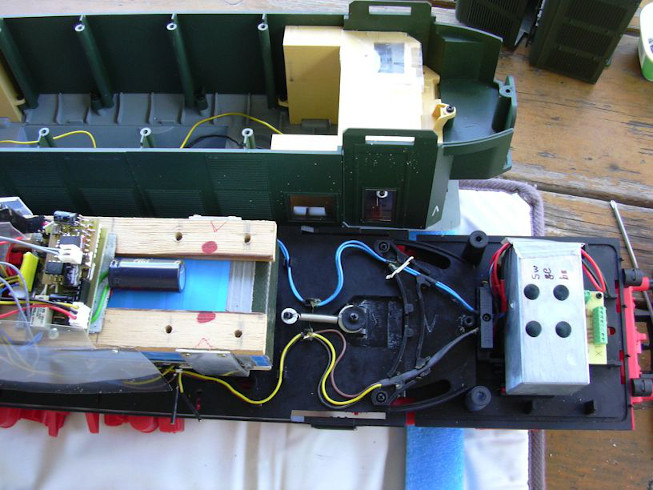
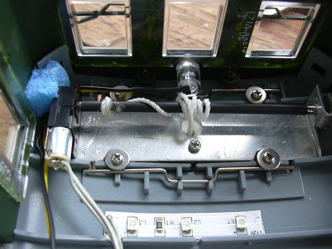
Here's a view at the first built-in electronic components. On the left is the "power supply board". The batteries are connected here. Each cell also has its own fuse in the form of a soldered wire bridge with a predefined cross section. For caution causes and lack of experiences with LiFePo4 technology 4 Schottky diodes are used to avoid reversing the polarity of a cell in the event of deep discharge. This has proven to be unnecessary, especially since a adjustable battery undervoltage alarm module is used, which at Undervoltage in a cell generates a high-pitched alarm sound. The power board also contains the charging socket (XLR socket) to get for each cell its own charging circuit to avoid cell drift in the bud. The board also carries the battery switch and two Switching regulators. The step-up regulator generates around 18 V from the battery voltage for driving the locomotive. The stepdown controller generates from the Battery voltage 5 V to supply the electronics (except for the uncoupling servo and pantograph winches).
On the far right handside there is the speed controller board in the version, already being used in a number of garden railroad locomotives with Li-ion cells. The slot for the sound module (white 7-pin socket strip on the right above) is still empty, then stuck temporarily (for the purpose of provocation) a diesel sound module inside. There was also software with sound for that Fans and traction motors was intended to be used, but is off now. The decision was made to buy a locomotive sound decoder for copyright reasons to be used with E94 sound. This required a special software to control it but this software still has to be written yet. It is located in the additional module between the power board and the locomotive controller.
The additional module in the middle is still empty. Microcontrollers like (Tiny2313 / Tiny4313) and SD card sound module (WTV020-SD) on the photo. are not plugged in yet. At the bottom there is another stepdown regulator mounted, which controls the 5 V supplies for servos (uncoupler) and DC gear motors (pantographs). This is used for decoupling the power supply of microcontroller technology and high performance consumers to interference suppression and increase in reliability. The radio receiver which can be seen above the additional circuit board is the R6m from the Planet brand.
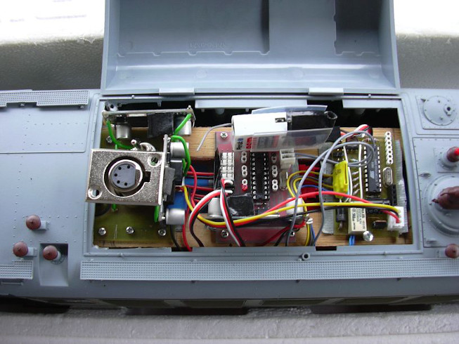
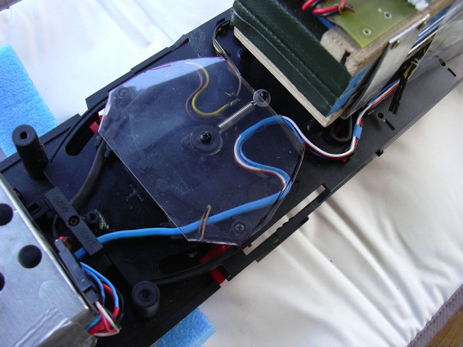
The electronic components have been arranged in a way that they can be opened when the roof hood is open. They were then covered with a stiff sheet covered to keep them protected from the fingers of curious viewers and helpers. Because the owner is sitting in his wheelchair the haandling of the locomotive relies on helpers who are not always familiar with the technology. That's why the battery switch is generous labeled too. The cover can be opened in a few simple steps removal, if this should ever be necessary. Below the charging socket a three-digit light shaft display can be seen. This shows at switched on locomotive alternatively (via switch) the battery voltage or the voltage behind the StepUp converter (18 V). This served primarily the observation under operating conditions and the detection of possible errors. You can see this on the right on the board of the locomotive controller aattached to sound module with Tiny85 microcontroller and audio amplifier LM386. It contains the already mentioned diesel sound. It is now removed again.
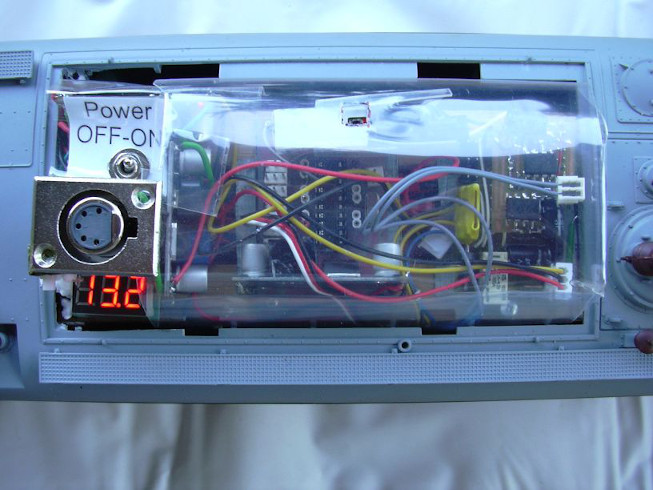
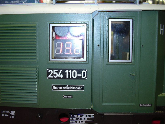
Here you can see the light shaft display when the locomotive is switched on. It is currently showing the battery voltage.
The "control center" can be covered with the roof hood, it is eng (ehhh "tight"), but works fine.
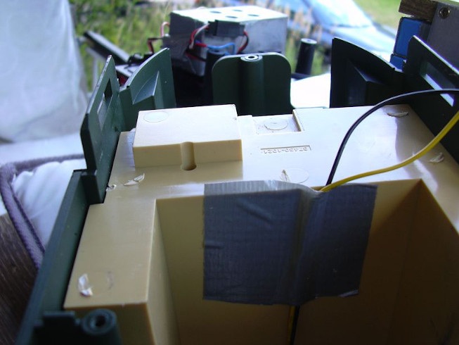
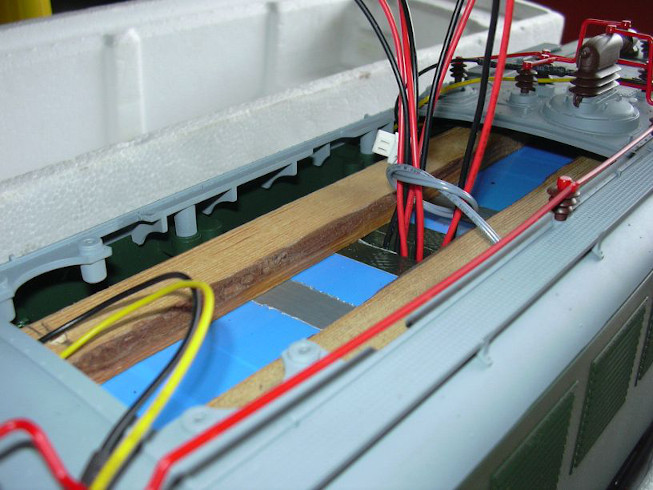
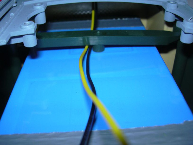
These are designed in such a rectangular and sharp-edged way that the cables get stuck there again and again. At first I wanted the cables with a stiff film to protect against nuisance, but the size off a half a millimeter was already too thick, the bogies had no more freedom of movement when the housing was closed, they were completely uptight.
So the foils had been thrown out again and the footwells were tackled with the flex:
The resulting opening was closed with packing tape. Now the cables have enough space and no longer interfere with anything.
The locomotive was then on the road for a long time without a pantograph and with a diesel sound, So to speak, for a long-term test of the chassis and ekeltronics, eh electronics. In the meantime, the software for the controller in the add-on module worked. This receives its information from the locomotive controller RS232 (TTL level). The information includes direction of travel and Speed ??step, actuation of the function keys of the channel on which the locomotive is logged in and presses the entire management keyboard (Digits, login buttons, switch buttons). Logging in and out is also possible communicated. Thus the additional module has all the information that the locomotive over the radio.
From this flood of information, the additional module now filters out what it is responsible for. First of all, there are two servo functions for Uncoupler (but only one servo is installed) and two H-bridges for the DC gear motors of the pantograph drives. For both H-bridges became an L293 (Stepperdriver) on one piece Hole grid board inserted. Furthermore, the additional module takes care of it to some operating states or their changes and can be in certain Situations to the WTV020-SD (monophonic sound module) orders for play back one (of max. 512) sound. Furthermore, with enter a two-digit number using the numeric keypad and press Key "F", actually for routes of a turnout control one of 100 sounds was intended to be triggered. In addition to serious sounds and announcements, there is also a few meaningless sayings, such as "Beware of the train, the platform is leaving ...". The software of the add-on module is not finished yet, because it should still be finished DCC output can be expanded to include a DCC locomotive sound decoder address, who should then output the driving noises. However, additional sounds that can be triggered via the keyboard remain active.

In the course of the renovation in April 2014, the programmable battery alarm module had been included. There was also another board with 2 micro-relays necessary to activate the alarm module when the locomotive is switched off all poles (except ground) are disconnected from the battery. The alarm module was mounted behind a window in the engine room so that one can see the battery status can also be read from the outside:
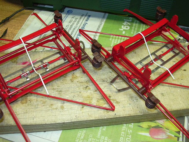
Since now the pantographs should be back on the roof and so should they still had to be moved, these were first attached with epoxy glue Wire eyelets glued on to fasten the pull cords. After star twine when it had proved too rough and got tangled up, tile string had been used that is too thick and smooth to tangle.
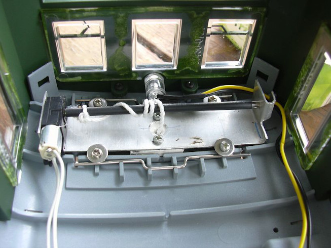
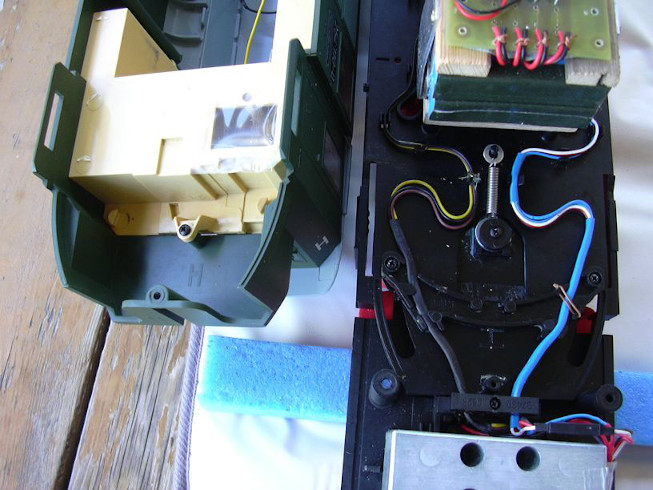
Small DC gear motors were used as winches for the pantographs used, the cable drum is a 3 mm diameter shaft that is connected to Shrink tubing is covered. The L293, which controls the motors, is operated with 5 V. The front driver's cab also received one Cab lighting. In doing so, a segment of a warm white LED light strip used. That the middle LED is soldered crooked (it wasn't me !!! alone !!!), I only see it in the photo noticed.
A decoupler offered by Bertram Heyn was used. The Servo was bolted to the weight of the bogie (holes drilled, thread cut, plate remainder as a clamp over it). The The supplied fishing line was bent through the supplied warm Plastic pipe led to the uncoupler. In addition, a hole had to be made in the bogie frame to be drilled. The servos are precisely adjusted from the hand-held transmitter of the radio remote control via menu, with the feedback takes place via the voice output of the WTV020-SD module. The assignment of the sounds for the operating situations are made via a menu with voice output.
As part of the renovation in April 2014, the drive units were exchanged for the new version. These are now with ball-bearing Bühler motors with two gear scrolls and appropriately revised gears and axles, what that Driving behavior significantly improved.
Here you can see the locomotive in its diesel era...
Here is the first major test drive with the additional module...